
Users Guide
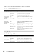
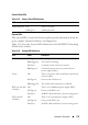
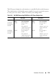
Table Of Contents
- Introduction
- Switch Feature Overview
- System Management Features
- Multiple Management Options
- System Time Management
- Log Messages
- System Reset
- Integrated DHCP Server
- Management of Basic Network Information
- IPv6 Management Features
- Dual Software Images
- File Management
- Switch Database Management Templates
- Automatic Installation of Firmware and Configuration
- sFlow
- SNMP Alarms and Trap Logs
- CDP Interoperability Through ISDP
- Remote Monitoring (RMON)
- Stacking Features
- Security Features
- Configurable Access and Authentication Profiles
- Password-Protected Management Access
- Strong Password Enforcement
- TACACS+ Client
- RADIUS Support
- SSH/SSL
- Inbound Telnet Control
- Denial of Service
- Port Protection
- Captive Portal
- 802.1X Authentication (IEEE 802.1X)
- MAC-Based 802.1X Authentication
- 802.1X Monitor Mode
- Port Security
- Access Control Lists (ACLs)
- Time-Based ACLs
- IP Source Guard (IPSG)
- DHCP Snooping
- Dynamic ARP Inspection
- Protected Ports (Private VLAN Edge)
- Green Technology Features
- Power over Ethernet (PoE) Features
- PD Detection
- Legacy (Reduced Capacitor) Detection
- Classification
- Port Start Up
- Overload Detection and Port Shutdown
- Disconnect Detection
- IC Thermal Monitoring
- Over-Temperature Protection
- 4-Pair Ports
- IEEE 802.3bt Capability
- PoE Port Capabilities and Power Limits
- Key PoE Plus Features
- Power Over Ethernet (PoE) Support
- PoE Plus Support
- PoE 60W Support
- Powered Device Detection
- PoE Power Management Modes
- Power Management in Guard Band
- PoE Plus Default Settings
- Switching Features
- Flow Control Support (IEEE 802.3x)
- Head of Line Blocking Prevention
- Jumbo Frames Support
- Auto-MDI/MDIX Support
- VLAN-Aware MAC-based Switching
- Back Pressure Support
- Auto-negotiation
- Storm Control
- Port Mirroring
- Static and Dynamic MAC Address Tables
- Link Layer Discovery Protocol (LLDP)
- Link Layer Discovery Protocol (LLDP) for Media Endpoint Devices
- Connectivity Fault Management (IEEE 802.1ag)
- Cisco Protocol Filtering
- DHCP Layer-2 Relay
- Virtual Local Area Network Supported Features
- Spanning Tree Protocol Features
- Link Aggregation Features
- Routing Features
- Address Resolution Protocol (ARP) Table Management
- VLAN Routing
- IP Configuration
- Open Shortest Path First (OSPF)
- Border Gateway Protocol (BGP)
- Virtual Routing and Forwarding (VRF)
- BOOTP/DHCP Relay Agent
- IP Helper and DHCP Relay
- Routing Information Protocol
- Router Discovery
- Routing Table
- Virtual Router Redundancy Protocol (VRRP)
- Tunnel and Loopback Interfaces
- IPv6 Routing Features
- Quality of Service (QoS) Features
- Layer-2 Multicast Features
- Layer-3 Multicast Features
- System Management Features
- Hardware Overview
- Dell EMC Networking N1100-ON Series Switch Hardware
- Dell EMC Networking N1500 Series Switch Hardware
- Dell EMC Networking N2000 Series Switch Hardware
- Dell EMC Networking N2100-ON Series Switch Hardware
- Dell EMC Networking N2200-ON Series Switch Hardware
- N2200-ON Series Front Panel
- N2200-ON Series Rear Panel
- N2200X-ON Series Switch Ports
- N2200-ON Series Console Port
- N2200-ON Series USB Port
- N2200-ON Series Reset Button
- N2200-ON Series Port and System LEDs
- N2200-ON Series Stack Master LED and Stack Number Display
- N2200-ON Series Power Supplies
- N2200-ON Series LED Definitions
- Dell EMC Networking N3000E-ON Series Switch Hardware
- Dell EMC Networking N3100-ON Series Switch Hardware
- Dell EMC Networking N3200-ON Series Switch Hardware
- N3200-ON Series Front Panel
- N3200-ON Series Rear Panel
- N3200-ON Series Switch Ports
- N3200-ON Series Console Port
- N3200-ON Series USB Port
- N3200-ON Series Reset Button
- N3200-ON Series Port and System LEDs
- N3200-ON Series Stack Master LED and Stack Number Display
- N3200-ON Series Power Supplies
- N3200-ON Series LED Definitions
- Switch MAC Addresses
- Using Dell EMC OpenManage Switch Administrator
- Using the Command-Line Interface
- Default Settings
- Setting the IP Address and Other Basic Network Information
- Stacking
- Stacking Overview
- Dell EMC Networking Stacking Compatibility
- How is the Stack Master Selected?
- Adding a Switch to the Stack
- Removing a Switch from the Stack
- How is the Firmware Updated on the Stack?
- What is Stacking Standby?
- What is Nonstop Forwarding?
- Switch Stack MAC Addressing and Stack Design Considerations
- NSF Network Design Considerations
- Why is Stacking Needed?
- Default Stacking Values
- Managing and Monitoring the Stack (Web)
- Managing the Stack (CLI)
- Stacking and NSF Usage Scenarios
- Stacking Overview
- Authentication, Authorization, and Accounting
- AAA Introduction
- Authentication
- Authorization
- Accounting
- IEEE 802.1X
- What is IEEE 802.1X?
- What are the 802.1X Port Authentication Modes?
- What are Authentication Host Modes
- What is MAC Authentication Bypass?
- What is the Role of 802.1X in VLAN Assignment?
- What is Monitor Mode?
- How Does the Authentication Server Assign DiffServ Policy or ACLs?
- What is the Internal Authentication Server?
- Default 802.1X Values
- Configuring IEEE 802.1X (Web)
- Captive Portal
- Monitoring and Logging System Information
- System Monitoring Overview
- Default Log Settings
- Monitoring System Information and Configuring Logging (Web)
- Device Information
- System Health
- System Resources
- Unit Power Usage History
- Integrated Cable Test for Copper Cables
- Optical Transceiver Diagnostics
- Log Global Settings
- RAM Log
- Log File
- SYSLOG Server
- Email Alert Global Configuration
- Email Alert Mail Server Configuration
- Email Alert Subject Configuration
- Email Alert To Address Configuration
- Email Alert Statistics
- Monitoring System Information and Configuring Logging (CLI)
- Logging Configuration Examples
- Managing General System Settings
- System Settings Overview
- Default General System Information
- Configuring General System Settings (Web)
- System Information
- CLI Banner
- SDM Template Preference
- Clock
- SNTP Global Settings
- SNTP Authentication
- SNTP Server
- Summer Time Configuration
- Time Zone Configuration
- Card Configuration
- Slot Summary
- Supported Cards
- Power Over Ethernet Global Configuration
- Power Over Ethernet Unit Configuration
- Power Over Ethernet Interface Configuration
- Configuring System Settings (CLI)
- General System Settings Configuration Examples
- SNMP
- Images and File Management
- DHCP and USB Auto-Configuration
- Auto Configuration Overview
- What Is USB Auto Configuration?
- What Files Does USB Auto Configuration Use?
- How Does USB Auto Configuration Use the Files on the USB Device?
- What Is the Setup File Format?
- What Is the DHCP Auto Configuration Process?
- Monitoring and Completing the DHCP Auto Configuration Process
- What Are the Dependencies for DHCP Auto Configuration?
- Default Auto Configuration Values
- Managing Auto Configuration (Web)
- Managing Auto Configuration (CLI)
- Auto Configuration Example
- Auto Configuration Overview
- Monitoring Switch Traffic
- Traffic Monitoring Overview
- Default Traffic Monitoring Values
- Monitoring Switch Traffic (Web)
- sFlow Agent Summary
- sFlow Receiver Configuration
- sFlow Sampler Configuration
- sFlow Poll Configuration
- Interface Statistics
- Etherlike Statistics
- GVRP Statistics
- EAP Statistics
- Utilization Summary
- Counter Summary
- Switchport Statistics
- RMON Statistics
- RMON History Control Statistics
- RMON History Table
- RMON Event Control
- RMON Event Log
- RMON Alarms
- Port Statistics
- LAG Statistics
- Port Mirroring
- Monitoring Switch Traffic (CLI)
- Traffic Monitoring Examples
- iSCSI Optimization
- iSCSI Optimization Overview
- What Does iSCSI Optimization Do?
- What Occurs When iSCSI Optimization Is Enabled or Disabled?
- How Does the Switch Detect iSCSI Traffic Flows?
- How Is Quality of Service Applied to iSCSI Traffic Flows?
- How Does iSCSI Optimization Use ACLs?
- What Information Does the Switch Track in iSCSI Traffic Flows?
- How Does iSCSI Optimization Interact With Dell EqualLogic and Compellent Arrays?
- How Does iSCSI Optimization Interact with Other SAN Arrays?
- Default iSCSI Optimization Values
- Configuring iSCSI Optimization (Web)
- Configuring iSCSI Optimization (CLI)
- iSCSI Optimization Configuration Examples
- iSCSI Optimization Overview
- Port Characteristics
- Port and System Security
- Access Control Lists
- VLANs
- VLAN Overview
- Default VLAN Behavior
- Configuring VLANs (Web)
- Configuring VLANs (CLI)
- Creating a VLAN
- Configuring VLAN Settings for a LAG
- Configuring Double VLAN Tagging
- Configuring MAC-Based VLANs
- Configuring IP-Based VLANs
- Configuring a Protocol-Based VLAN
- Configuring GVRP
- Configuring Voice VLANs
- Configuring a Voice VLAN (Extended Example)
- Enterprise Voice VLAN Configuration With QoS
- MLAG with RPVST and Voice VLAN
- Assigning an 802.1p Priority to VLAN Traffic
- Configuring a Private VLAN
- Configuring Inter-Switch Private VLANs
- VLAN Configuration Examples
- Spanning Tree Protocol
- Discovering Network Devices
- Port-Based Traffic Control
- Layer-2 Multicast Features
- L2 Multicast Overview
- Snooping Switch Restrictions
- Default L2 Multicast Values
- Configuring L2 Multicast Features (Web)
- Multicast Global Parameters
- Bridge Multicast Group
- MFDB Summary
- MRouter Status
- General IGMP Snooping
- Global Querier Configuration
- VLAN Querier
- VLAN Querier Status
- MFDB IGMP Snooping Table
- MLD Snooping General
- MLD Snooping Global Querier Configuration
- MLD Snooping VLAN Querier
- MLD Snooping VLAN Querier Status
- MFDB MLD Snooping Table
- MVR Global Configuration
- MVR Members
- MVR Interface Configuration
- MVR Statistics
- GARP Timers
- GMRP Parameters
- MFDB GMRP Table
- Configuring L2 Multicast Features (CLI)
- Case Study on a Real-World Network Topology
- Connectivity Fault Management
- Ethernet Ring Protection
- Ethernet Ring Protection Switching Port Role
- R-APS Channel
- Traffic Channel
- Ring Scope
- Ethernet Ring Protection Port Status
- Ethernet Ring Protection Timers
- Revertive and Non-Revertive Operation Modes
- ERPS Subrings
- Topology Change Notification
- Protection Switching Triggers
- Ring Failure Detection
- Ring Protection Example
- Snooping and Inspecting Traffic
- Traffic Snooping and Inspection Overview
- Default Traffic Snooping and Inspection Values
- Configuring Traffic Snooping and Inspection (Web)
- DHCP Snooping Configuration
- DHCP Snooping Interface Configuration
- DHCP Snooping VLAN Configuration
- DHCP Snooping Persistent Configuration
- DHCP Snooping Static Bindings Configuration
- DHCP Snooping Dynamic Bindings Summary
- DHCP Snooping Statistics
- IPSG Interface Configuration
- IPSG Binding Configuration
- IPSG Binding Summary
- DAI Global Configuration
- DAI Interface Configuration
- DAI VLAN Configuration
- DAI ACL Configuration
- DAI ACL Rule Configuration
- DAI Statistics
- Configuring Traffic Snooping and Inspection (CLI)
- Traffic Snooping and Inspection Configuration Examples
- Link Aggregation
- MAC Addressing and Forwarding
- DHCP Server Settings
- IP Routing
- Routing Interfaces
- Layer-2 and Layer-3 Relay Features
- OSPF and OSPFv3
- OSPF Overview
- OSPF Feature Details
- OSPFv3 MIB Support
- Default OSPF Values
- Configuring OSPF Features (Web)
- OSPF Configuration
- OSPF Area Configuration
- OSPF Stub Area Summary
- OSPF Area Range Configuration
- OSPF Interface Statistics
- OSPF Interface Configuration
- OSPF Neighbor Table
- OSPF Neighbor Configuration
- OSPF Link State Database
- OSPF Virtual Link Configuration
- OSPF Virtual Link Summary
- OSPF Route Redistribution Configuration
- OSPF Route Redistribution Summary
- NSF OSPF Configuration
- Configuring OSPFv3 Features (Web)
- OSPFv3 Configuration
- OSPFv3 Area Configuration
- OSPFv3 Stub Area Summary
- OSPFv3 Area Range Configuration
- OSPFv3 Interface Configuration
- OSPFv3 Interface Statistics
- OSPFv3 Neighbors
- OSPFv3 Neighbor Table
- OSPFv3 Link State Database
- OSPFv3 Virtual Link Configuration
- OSPFv3 Virtual Link Summary
- OSPFv3 Route Redistribution Configuration
- OSPFv3 Route Redistribution Summary
- NSF OSPFv3 Configuration
- Configuring OSPF Features (CLI)
- Configuring OSPFv3 Features (CLI)
- OSPF Configuration Examples
- Configuring OSPF VRFs
- VRF
- RIP
- VRRP
- BGP
- Overview
- BGP Operations
- Decision Process Overview
- Path Attributes
- BGP Finite State Machine (FSM)
- Detecting Loss of Adjacency
- Authentication
- Outbound Update Groups
- Removing Private AS Numbers
- Templates
- Resolving Interface Routes
- Originating BGP Routes
- Equal Cost Multipath (ECMP)
- BGP Next-Hop Resolution
- Address Aggregation
- Routing Policy
- Inbound Policy
- Outbound Policy
- Routing Policy Changes
- BGP Timers
- Communities
- Routing Table Overflow
- Route Reflection
- VRF Support
- BGP Neighbor Configuration
- Extended Communities
- VPNv4/VRF Route Distribution via MP-BGP
- IPv6
- BGP Limitations
- BGP Configuration Examples
- Bidirectional Forwarding Detection
- Unicast Reverse Path Forwarding
- IPv6 Routing
- DHCPv6 Server Settings
- Differentiated Services
- Class-of-Service
- Auto VoIP
- IPv4 and IPv6 Multicast
- L3 Multicast Overview
- Default L3 Multicast Values
- Configuring General IPv4 Multicast Features (Web)
- Configuring IPv6 Multicast Features (Web)
- Configuring IGMP and IGMP Proxy (Web)
- Configuring MLD and MLD Proxy (Web)
- MLD Global Configuration
- MLD Routing Interface Configuration
- MLD Routing Interface Summary
- MLD Routing Interface Cache Information
- MLD Routing Interface Source List Information
- MLD Traffic
- MLD Proxy Configuration
- MLD Proxy Configuration Summary
- MLD Proxy Interface Membership Information
- Detailed MLD Proxy Interface Membership Information
- Configuring PIM for IPv4 and IPv6 (Web)
- Configuring DVMRP (Web)
- Configuring L3 Multicast Features (CLI)
- Configuring and Viewing IPv4 Multicast Information
- Configuring and Viewing IPv6 Multicast Route Information
- Configuring and Viewing IGMP
- Configuring and Viewing IGMP Proxy
- Configuring and Viewing MLD
- Configuring and Viewing MLD Proxy
- Configuring and Viewing PIM-DM for IPv4 Multicast Routing
- Configuring and Viewing PIM-DM for IPv6 Multicast Routing
- Configuring and Viewing PIM-SM for IPv4 Multicast Routing
- Configuring and Viewing PIM-SM for IPv6 Multicast Routing
- Configuring and Viewing DVMRP Information
- L3 Multicast Configuration Examples
- Multiple Registration Protocol
- OpenFlow
- Dell EMC Networking Python Support
- Appendix
- Index

138 Hardware Overview
Power Consumption for N2000 Series PoE Switches
Table 3-17 shows power consumption data for the PoE-enabled switches.
Fan Solid green The fan is powered and is operating at the
expected RPM.
Solid red A fan failure has occurred.
Stack Master Off The switch is not stack master.
Solid green The switch is master for the stack.
Temp Solid green The switch is operating below the threshold
temperature.
Solid red The switch temperature exceeds the threshold
of 75°C.
Stack No. – Switch ID within the stack.
Table 3-17. Power Consumption
Model Input
Voltage
Power Supply
Configuration
Max Steady
Current
Consumption (A)
Max Steady
Power (W)
Dell EMC
Networking
N2024P
100V Main PSU+EPS PSU 8.9 890.0
110V Main PSU+EPS PSU 8.3 913.0
120V Main PSU+EPS PSU 7.6 912.0
220V Main PSU+EPS PSU 4.0 880.0
240V Main PSU+EPS PSU 3.6 873.6
Dell EMC
Networking
N2048P
100V Main PSU+EPS PSU 17.8 1780.0
110V Main PSU+EPS PSU 15.8 1740.2
120V Main PSU+EPS PSU 14.5 1740.0
220V Main PSU+EPS PSU 7.7 1687.4
240V Main PSU+EPS PSU 7.1 1704.0
Table 3-16. System LED Definitions (Continued)
LED Color Definition