Dell EMC PowerSwitch N2200-ON Series Installation Guide December 2020 Rev.
Notes, cautions, and warnings NOTE: A NOTE indicates important information that helps you make better use of your product. CAUTION: A CAUTION indicates either potential damage to hardware or loss of data and tells you how to avoid the problem. WARNING: A WARNING indicates a potential for property damage, personal injury, or death. © 2020 Dell Inc. or its subsidiaries. All rights reserved. Dell, EMC, and other trademarks are trademarks of Dell Inc. or its subsidiaries.
Contents Chapter 1: About this guide........................................................................................................... 5 Related documents............................................................................................................................................................. 6 Information symbols............................................................................................................................................................
Components....................................................................................................................................................................... 33 AC or DC power supply installation.............................................................................................................................. 35 AC or DC power supply replacement......................................................................................................................
1 About this guide This guide provides site preparation recommendations, step-by-step procedures for rack mounting and desk mounting your switch, inserting modules, and connecting to a power source. CAUTION: To avoid electrostatic discharge (ESD) damage, wear grounding wrist straps when handling this equipment. NOTE: Only trained and qualified personnel can install this equipment. Read this guide before you install and power up this equipment. This equipment contains two power cords.
Related documents For more information about the N2200-ON Series, see the following documents: ● Dell EMC PowerSwitch N2200-ON Series Warnings Guide ● Dell EMC PowerSwitch N2200-ON Series Setup Placemat ● Dell EMC PowerSwitch N2200-ON Series Release Notes ● Open Networking Hardware Diagnostic Guide N2200-ON and N3200-ON Series Switches ● External Power Supply (EPS) Installation for the Dell EMC PowerSwitch N2200-ON and N3200-ON Series Switches NOTE: For the most recent documentation, see Dell EMC support: w
2 N2200-ON Series switch The following sections describe the Dell EMC N2200-ON Series (N2224X-ON, N2224PX-ON, N2248X-ON, and N2248PX-ON) switches: Topics: • • • • • • • Introduction Features Physical dimensions LED display Prerequisites N2200-ON Series switch configurations Luggage tag Introduction The N2200-ON Series switches are one rack unit (1U), full-featured fixed form-factor compact switches. Table 1.
1. 3. 5. 7. 9. Luggage tag RJ45 serial management port USB Type-A port MicroUSB Type-B port 25G SFP28 ports 2. 4. 6. 8. 2.5GBASE-T RJ45 multigigabit ports RJ45 Ethernet console port Stack ID Status LEDs N2224PX-ON I/O-side view 1. Luggage tag 3. 5. 7. 9. RJ45 serial management port USB Type-A port MicroUSB Type-B port 25G SFP28 ports 2. 2.5GBASE-T RJ45 ports: ● First 12 ports with 802.at (30W) PoE ● Second 12 ports with 802.3bt Type-3 (60W) PoE 4. RJ45 Ethernet console port 6. Stack ID 8.
7. MicroUSB Type-B port 9. 25G SFP28 ports 8. Status LEDs N2248PX-ON I/O-side view 1. Luggage tag 3. 5. 7. 9. RJ45 serial management port USB Type-A port MicroUSB Type-B port 25G SFP28 ports 2. 2.5GBASE-T RJ45 ports: ● First 24 ports with 802.at (30W) PoE ● Second 24 ports with 802.3bt Type-3 (60W) PoE 4. RJ45 Ethernet console port 6. Stack ID 8. Status LEDs N2200-ON Series PSU-side views N2224X-ON PSU-side view 1. 40G QSFP+ stacking ports 2. Fans 3. AC or DC PSUs N2224PX-ON PSU-side view 1.
N2248X-ON PSU-side view 1. 40G QSFP+ stacking ports 2. Fans 3. AC or DC PSUs N2248PX-ON PSU-side view 1. 40G QSFP+ stacking ports 3. Input for external power shelf (MPS-1S shelf and MPS-3S shelf) 2. Fans 4. AC or DC PSUs Features The N2200-ON Series switches offer the following features: ● Ports: ○ N2224X-ON—1 U, 24 multigigabit ports 2.5GBASE-T RJ24, four ports 25G SFP28, and two ports of 40G QSFP+ for stacking ○ N2224PX-ON—1 U, 24 multigigabit ports 2.5GBASE-T RJ24: 12 ports of 802.
Physical dimensions The N2200-ON Series switches have the following physical dimensions, excluding the PSU and fan tray handle: ● 1.71 in x 17.09 in x 15.75 in (H x W x D) ● 43.5 mm x 434 mm x 400 mm (H x W x D) (PSU and fan tray handle adds 1.18 in or 30 mm) LED display The N2200-ON Series switch includes LED displays on the I/O side of the switch. This section describes open networking installation environment (ONIE) LED behaviors. Some LED behaviors may change after you install your software.
Table 2.
Table 5. 2.5G Base-T PoE port LEDs (continued) LED Description ● Solid green—Link operating at maximum speed, autonegotiated/forced to 2.5GBase-T mode ● Solid yellow—Link operating at a lower speed, autonegotiated/forced to 10/100/1000MBase-T ● Flashing green, ~30ms—Port activity Activity LED ● ● ● ● Off—No activity and PoE power off Solid yellow—No port activity and PoE power on Flashing green—port activity and PoE power off Flashing yellow—port activity and PoE power on Table 6. 2.
Prerequisites The following is a list of components that are required for successful switch installation: NOTE: For detailed installation instructions, see Site preparations and N2200-ON Series switch installation.
Luggage tag The switch has a pull-out tag, which is known as a luggage tag, on the PSU-side of the switch. The front of the luggage tag includes switch ID information. The back of the luggage tag includes a QRL that takes you to a How-To site where you can watch videos about racking the switch, replacing components, configuring port channels, and so on. N2224PX-ON and N2224X-ON luggage tag 1. Product ID QRL 3. SVC tag 5. Exp Svc code 2. Product information QRL 4.
1. Product ID QRL 3. SVC tag 5. Exp Svc code 16 N2200-ON Series switch 2. Product information QRL 4.
3 Site preparations The N2200-ON Series switch is suitable for installation as part of a common bond network (CBN). You can install the switch in: ● Network telecommunication facilities ● Data centers ● Other locations where the National Electric Code (NEC) applies NOTE: Install the switch into a rack or cabinet before installing any additional components such as cables or optics.
Rack mounting When you prepare your equipment rack, ensure that the rack is grounded. Ground the equipment rack to the same ground point the power service in your area uses. The ground path must be permanent. Switch ground Dell Technologies recommends you ground your switch. Use the N2200-ON Series switch in a common bond network (CBN). Connect the grounding cables as described in N2200-ON Series switch installation.
NOTE: Software controls the module power. You do not see module LEDs when the switch powers up in ONIE. Storing components If you do not install your N2200-ON Series switch and components immediately, properly store the switch and all components using these guidelines: ● Storage location temperature must remain constant. The storage range is from -40°C to 70°C (-40°F to 158°F). ● Store on a dry surface or floor, away from direct sunlight, heat, and air conditioning ducts.
4 N2200-ON Series switch installation To install the N2200-ON Series switch, complete the installation procedures in the order that is presented in this chapter. Always handle the switch and components with care. Avoid dropping the switch or its field replaceable units (FRUs). NOTE: ESD damage can occur if components are mishandled. Always wear an ESD-preventive wrist or heel ground strap when handling the N2200-ON Series switch and components.
3. Carefully remove the switch from the container and place it on a secure and clean surface. 4. Remove all packing material. 5. Inspect the product and accessories for damage. Rack or cabinet hardware installation You may either place the switch on a rack shelf or mount the switch directly into a 19" wide, EIA-310- E-compliant rack. Rack mounting includes four-post, two-post, or threaded mounts. WARNING: This document is a condensed reference.
3. Attach the other end of the ground cable to a suitable ground point such as the rack or cabinet. The rack installation ears are not a suitable grounding point. Desktop One mounting option is to place the N2200-ON Series switch on a desktop. The mounting supplies for this installation ship with the switch. 1. Locate the four rubber feet shipped with the switch. 2. Remove the paper backing on the bottom of a rubber foot. 3.
4. Slide the switch into the two-post rack until the mounting bracket ears line up with the rack. 5. Attach the switch to the two-post rack using two number 12-24 screws on each side. To uninstall the switch from the rack, unscrew the four number 12-24 rackmount screws. Two-post flush-mount switch installation NOTE: To install an external power supply, see the External Power Supply (EPS) Installation for the Dell EMC PowerSwitch N2200-ON and N3200-ON Series Switches at www.dell.com/support. 1.
4. Slide the switch into the two-post rack until the mounting bracket ears line up with the rack. 5. Attach the switch to the two-post rack using two number 12-24 screws on each side. To uninstall the switch from the rack, unscrew the four number 12-24 rackmount screws. Wall- or ceiling-mount switch installation This installation procedure is for the full-width N2200-ON Series switches only.
5. Drill eight 8 mm (0.3 in) holes in the wall or ceiling at the pencil marks. 6. Install the eight anchors into the holes. 7. Screw one M5 screw on each corner, four screws total, into the anchors, leaving approximately 5 mm (0.20 in) gap between the anchor and the screw. 8. Slide the switch onto the screws and tighten the screws to secure the switch in place. Torque the screws to 24 in-lbs. Wall mount 9. Screw the remaining four M5 screws into the anchors and tighten the screws.
Wall mount ceiling mount One RU ReadyRails installation Install the N2200-ON Series switch using one of the following installation instructions. You can install the ReadyRails system using the 1U tool-less square-hole method or one of three possible 1U threaded round-hole methods. The tooled installation methods include two-post flush mount, two-post center mount, or four-post threaded mount. NOTE: You must order the ReadyRails mounting supplies for this installation separately.
Figure 2. Separate rails 1U Tool-less mount ReadyRail installation NOTE: For more installation instructions, see the installation labels attached to the rail assembly. 1. Face the ReadyRails flange ears facing outward. Place one rail between the left and right vertical posts. Align and seat the back flange rail pegs in the back vertical post flange. The center extractions show how the pegs appear in both the square and nonthreaded round holes. 2.
NOTE: Be sure that the rails click into place and are secure. 3. Repeat this procedure for the second rail. To remove each rail, pull on the latch release on each flange ear and unseat each rail. Flush-mount ReadyRail installation NOTE: For more installation instructions, see the installation labels attached to the rail assembly. 1. Remove the latch castings from the front side of each ReadyRails assembly, item 1.
2. Slide the back bracket towards the post. Secure it to the post flange with two user-supplied screws, items 2 and 3. 3. Repeat this procedure for the second rail. Threaded ReadyRails installation NOTE: For more installation instructions, see the installation labels attached to the rail assembly. 1.
Figure 3. Four-post threaded round-hole installation 2. Attach the front and back flanges for each rail to the post flanges with two user-supplied screws at each end. Optics installation The N2200-ON Series has QSFP+ and SFP28 optical ports. For a list of supported optics, see the specification sheets at www.dell.com/support or contact your Dell EMC Sales representative. CAUTION: ESD damage can occur if components are mishandled.
Switch start-up Supply power to the N2200-ON Series switch after you install your switch. Dell Technologies recommends reinspecting your switch before powering it up. Verify the following: ● Optional: The equipment is properly secured to the rack and properly grounded. ● Optional: The equipment rack is properly mounted and grounded. ● The ambient temperature around the unit, which may be higher than the room temperature, is within the limits that are specified for the N2200-ON Series switch.
9. Establish a connection to the switch CLI. 10. Confirm that the software version of the replacement switch is the same as the previously installed switch. show version If the software versions do not match, upgrade the replacement switch software using the procedure included with the firmware download. 11. Copy the backed-up switch configuration to the new switch. copy tftp://hostip/filepath running-config NOTE: For firmware update procedures, see the most current switch-specific release notes at www.
5 Power supply The N2200-ON Series switch ships with one hot-swappable AC power supply. You can order a second AC PSU separately. If you require DC power, you can order one or two DC power supply units.
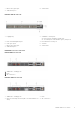
1. PSUs—PSU1 is near the center of the switch; PSU2 is on the right edge of the switch. N2224X-ON PSUs 1. PSUs—PSU1 is near the center of the switch; PSU2 is on the right edge of the switch. N2248PX-ON PSUs 1. PSUs—PSU1 is near the center of the switch; PSU2 is on the right edge of the switch. N2248X-ON PSUs 1. PSUs—PSU1 is near the center of the switch; PSU2 is on the right edge of the switch.
NOTE: To comply with the GR-1089 Lightning Criteria for Equipment Interfacing with AC or DC Power Ports, use an external surge protection device (SPD) at the AC or DC input of the router. AC power cable retainer For hot-swappable PSUs, after you have connected the power cable to the switch, use the included black power-cable tie to secure the cable in place. PSU LEDs ● Solid green—PSU input is OK. ● Flashing green blink at 1Hz—PSU is in a faulty state. ● Off—PSU is off.
1. PSU N2248PX-ON PSU installation 1. PSU N2248X-ON PSU installation 1. PSU NOTE: The N2200-ON Series switch powers up when you connect the cables between the power supply and the power source.
AC or DC power supply replacement CAUTION: Disconnect the power cable before removing the power supplies. Also, disconnect all power cables before servicing. NOTE: The PSU slides into the slot smoothly. Do not force a PSU into a slot as this action may damage the PSU or the N2200-ON Series switch. NOTE: If a PSU fails, you must replace the entire unit. There are no field serviceable components in the PSU. To request a hardware replacement, see www.dell.com/support/. 1.
3. Use a flat-head screwdriver to tighten the screws that secures the bare wires into the wiring block. 4. Secure the 550W DC power source wires to the other side of the wiring block, see steps 1 and 3. NOTE: Do not cross the wires. 5. Insert the 550W DC power connector into the power socket of the 550W DC PSU. Ensure that the connector pins firmly seat and you hear the click of the left and right levered power connector clamps lock into place.
5. Attach the blue wire and black wire to the PSU socket. Secure the wires with the two M4 screws. NOTE: Attach the blue wire to the V- terminal. Attach the black wire to the V+ terminal. 6. Return the plastic cover back to the PSU socket. 7. Attach the yellow and green wire to the PSU GND. Secure the wire with the M5 screw. NOTE: To uninstall the cable from the 1300W DC PSU, remove the plastic cover and unscrew the M4 and M5 screws. Pull the 1300W DC cable out from the 1300W DC PSU socket.
Connect the EPS shelf NOTE: For more information about the external power supply (EPS), see External Power Supply (EPS) Installation for the Dell EMC PowerSwitch N2200-ON and N3200-ON Series Switches at www.dell.com/support. NOTE: The EPS power cable supports a maximum of 2400 W. If you require more power than 2400 W, you must connect two EPS power cables. To connect the EPS shelf to the switch, use the EPS power cable. 1. Unscrew the DC power cover from the rear of the switch.
MPS-3S shelf 3. Connect the EPS power cable to the EPS-DC-In on the switch. Torque the screw to 10 in-lbs.
Two EPS power cables connected 4. Connect the other end of the DC cable to either a MPS-1S shelf or MPS-3S shelf. Torque the screw to 10 in-lbs. One EPS power cable connected to a MPS-1S shelf.
Two EPS power cables connected to a MPS-3S shelf 5. Repeat until all EPS power cables are connected. To disconnect an EPS power cable, unscrew the cable and disconnect the cable from the switch.
6 Fans The N2200-ON Series switch comes from the factory with two or three pluggable fan modules. ● N2224X-ON and N2224PX-ON—Two fan modules ● N2248X-ON and N2248PX-ON—Three fan modules The N2224X-ON and N2248X-ON switches support two airflow direction options. Do not mix airflow types in a switch; you can use only a single airflow direction in a switch. If the airflow directions are mismatched, you must correct the mismatched airflow direction.
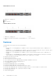
1. Fans—Fan1 is near the left edge of the switch; Fan2 is near the center of the switch. N2248PX-ON fan modules 1. Fans—Fan1 is near the left edge of the switch; Fan3 is near the center of the switch. N2248X-ON fan modules 1. Fans—Fan1 is near the left edge of the switch; Fan3 is near the center of the switch. Fan LEDs ● Solid green—Fan input is OK. ● Flashing green blink at 1Hz—Fan is in a faulty state. ● Off—Fan is off.
1. Fan N2224X-ON fan installation 1. Fan N2248PX-ON fan installation 1.
1. Fan Fan module replacement To request a hardware replacement, see www.dell.com/support/. 1. Take the replacement fan module out of the shipping box. 2. Slide the installed fan module out of the bay. 3. Slide the replacement module into the bay.
7 Management ports The N2200-ON Series switch provides three ports for management and one USB flash drive mount for file transfers. NOTE: The output examples in this section are for reference only. Your output may vary. Topics: • • • RJ45 console port access MicroUSB Type-B console port access USB storage mount RJ45 console port access For the N2200-ON Series switch, the management ports are on the I/O-side of the switch. N2224PX-ON and N2224X-ON management ports 1.
Alternately, install the DB-9 cable into other data terminal equipment (DTE) server hardware. 3. Use the following settings to make the serial port connection: ● ● ● ● ● 115200 baud rate No parity Eight data bits One stop bit No flow control MicroUSB Type-B console port access The MicroUSB type-B console port is on the I/O side of the switch. NOTE: The N2200-ON Series switches use the Silicon Labs CP2102 USB-B chip.
For USB storage: Disk /dev/sdb: 30.9 GB, 30942946304 bytes 64 heads, 32 sectors/track, 29509 cylinders Units = cylinders of 2048 * 512 = 1048576 bytes Device Boot Start End Blocks Id System 5. Mount the device /dev/sdb to the /mnt/usb directory. ONIE:/ # mount -t vfat /dev/sdb /mnt/usb NOTE: If the /mnt/usb directory is missing, the following message displays: mount: mounting /dev/ sdb on /mnt/usb failed: No such file or directory.
8 Installation using ONIE This section describes uninstalling an operating system and installing ONIE on your switch. For more information, see switchspecific information at www.dell.com/support. NOTE: Before you install an operating system, ensure that the switch has the most current ONIE and firmware version. To upgrade your switch, go to the Drivers and Downloads page for your switch at www.dell.com/support.
For downloading and updating ONIE from a URL ONIE: Embed ONIE For downloading and updating ONIE from a URL and erases any installed OS During the initial setup, the switch boots to ONIE Install. ONIE Install starts the discovery process. For more information, see Installation using ONIE. NOTE: For more information, see the Open Networking Hardware Diagnostic Guide for N2200-ON and N3200-ON Switches at www.dell.com/support.
00:14.0 Class 00:1f.4 Class 00:05.0 Class 00:1f.2 Class 00:1c.0 Class 00:1f.0 Class 02:00.0 Class 00:04.0 Class 01:00.0 Class ONIE:/ # 0106: 0c05: 0807: 0580: 0805: 0601: 0200: 0600: 0200: 8086:19c2 8086:19df 8086:19a2 8086:19de 8086:19db 8086:19dc 8086:1533 8086:19a1 14e4:b170 (NPU PCI detection) Uninstall an existing OS CAUTION: To install a networking operating system (NOS) on a switch that has a previously installed OS, you must first uninstall the existing OS.
| ONIE: Diag ONIE | +--------------------------------------------------------+ ● Install OS—Boots to the ONIE prompt and installs an NOS image using the Automatic Discovery process. When ONIE installs a new OS image, the previously installed image and configuration are deleted. ● Rescue—Boots to the ONIE prompt and enables manual installation of an NOS image or ONIE update. ● Uninstall OS—Deletes the contents of all disk partitions, including the NOS configuration, except ONIE and diagnostics.
Info: Fetching tftp://xx.xx.xx.x/onie-installer ... ONIE: Executing installer: tftp://xx.xx.xx.x/onie-installer ... ... ... Press or to enter setup. Welcome to GRUB! Manual NOS installation If you do not use the ONIE-based automatic installation of a NOS image and if a DHCP server is not available, you can manually install the image. Configure the Management port and provide the software image file to start the installation. 1. Save the NOS software image on an SCP/TFTP/FTP server. 2.
9 Specifications This section lists the N2200-ON Series switch specifications. CAUTION: Operate the product at an ambient temperature not higher than 45°C (113°F). NOTE: For RoHS information, see Restricted Material Compliance. Topics: • • • • Chassis physical design PoE Budget Specifications IEEE standards Agency compliance Chassis physical design Table 10. Chassis physical design Parameter Specifications Height x Width x Depth measurements, excluding the PSU and ● 1.71 in x 17 in x 15.
Table 11. Environmental parameters (continued) Parameter Specifications Maximum non-operational altitude 39,370 feet (12,000 meters) Shock Dell EMC Spec SV0115 Table 12. Power consumption parameters Parameter Specifications Input voltage ● AC: 100–240 VAC 50/60 Hz ● DC: –40 VDC to –60 VDC Input current without PoE ● N2224X-ON: 2.46 Amps @ 110 VAC and 1.23 Amps @ 220 VAC ● N2224PX-ON: 2.4 Amps @ 110 VAC and 1.2 Amps @ 220 VAC ● N2248X-ON: 3.37 Amps @ 110 VAC and 1.
Table 14. DC power requirements (continued) Parameter Specifications ● N2248PX-ON: 28 A @ 48 V PoE Budget Specifications The following details the PoE budget specifications for high-line and low-line AC inputs and general guidelines on how to derive the available PoE budgets based on the PSUs you use.
● Two internal PSUs: PSU1 power output + PSU2 power output * 0.9 - maximum system power consumption ● One internal PSU + MPS-1S shelf: (PSU1 power output + MPS-1S PSU power output) * 0.85 - maximum system power consumption ● Two internal PSUs + MPS-1S shelf: (PSU1 power output + PSU2 power output + MPS-1S PSU power output) * 0.85 maximum system power consumption ● One internal PSU + MPS-3S shelf: (PSU1 power output + MPS-3S PSU(s) power output) * 0.
Figure 5. Canadian Department of Communication Statement European Union EMC directive conformance statement This product is in conformity with the protection requirements of EU Council Directive 2004/108/EC on the approximation of the laws of the Member States relating to electromagnetic compatibility. Dell EMC cannot accept responsibility for any failure to satisfy the protection requirements resulting from a non-recommended modification of this product, including the fitting of non-Dell EMC option cards.
Figure 7. Japan: warning label Korean certification of compliance Figure 8. Korean certification of compliance Figure 9. Korean package label Safety standards and compliance agency certifications ● CUS UL 60950-1, 2nd Edition ○ Meets or exceeds Hi Pot and Ground Continuity testing per UL 60950-1.
Electromagnetic compatibility Emissions ● ● ● ● ● ● ● ● ● ● International: CISPR32: Class A Australia/New Zealand: AS/NZS CISPR 32: Class A Canada: ICES-003, Issue-4, Class A Europe: EN55032: CISPR 32: Class A International: CISPR 32: Class A EN55032 Japan: VCCI V-3/2011.04, Class A Korea: KN32, Class A Taiwan: CNS13438, Class A USA: FCC CFR47 Part 15, Subpart B, Class A Immunity ● ● ● ● ● ● ● ● ● ● ● EN EN EN EN EN EN EN EN EN EN EN 300 386 v2.1.
In accordance with the European WEEE Directive, electrical and electronic equipment (EEE) is to be collected separately and to be reused, recycled, or recovered at end of life. Users of EEE with the WEEE marking per Annex IV of the WEEE Directive, as shown above, must not dispose of end of life EEE as unsorted municipal waste, but use the collection framework available to customers for the return, recycling and recovery of WEEE.
10 Dell EMC support The Dell EMC support site provides documents and tools to help you use Dell EMC equipment and mitigate network outages. Through the support site you can obtain technical information, access software upgrades and patches, download available management software, and manage your open cases. The Dell EMC support site provides integrated, secure access to these services. To access the Dell EMC support site, go to www.dell.com/support/.