
Users Guide

Link Aggregation 1071
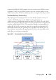
Supported topologies and the way traffic is handled in these topologies is
explained in the following sections.
The MLAG component uses the keep-alive protocol to select a primary and a
secondary device. The primary switch owns the MLAG member ports on the
secondary device. It handles the control plane functionality of supported
protocols for the MLAG member ports on the secondary.
Peer-Link
The peer-link is a crucial for MLAG operation. The peer-link must be
configured on a port-channel interface. Only one peer-link aggregation group
is allowed per peer switch and this peer-link is shared by all instances of
MLAG running on the two peer switches.
The peer-link is used for the following purposes:
• To transport keep-alive messages to the peer.
• To sync FDB entries learned on MLAG interfaces between the two MLAG
peer switches.
• To forward STP BPDUs and LACPDUs received on secondary MLAG
member ports to the primary MLAG switch.
• To send interface events related to MLAG interface and member ports
that occur on the secondary switch to the primary switch.
• To transfer MLAG control information between the primary and
secondary MLAG switches.
• To support a redundant forwarding plane in the case that all member ports
of an MLAG interface are down on an MLAG peer. In this case, traffic
received on the peer switch destined to the MLAG peer with the downed
ports is sent over the peer-link to the peer MLAG switch for forwarding to
the partner switch.
The peer-link is not utilized for partner traffic unless all LAG links connected
to an MLAG partner on a single MLAG peer are disrupted. It is strongly
recommended that the MLAG peer LAG consist of multiple physical links
with sufficient bandwidth to carry all traffic expected to be carried by either
of the MLAG peers.
The MLAG component internally configures filters so that traffic ingressing a
peer-link is blocked from egress on the peer MLAG switch. The filters are
modified when there is a failure of all the MLAG member interfaces on an