Dell EMC Networking Virtualization Overlay with BGP EVPN Deploying a BGP EPVN leaf-spine topology with VXLAN anycast gateways Abstract This guide covers the deployment of a physical Layer 3 leaf-spine underlay network and Layer 2 virtual network overlays with anycast gateways using VXLAN-based BGP EVPN.
Revisions Date Description May 2019 Initial release The information in this publication is provided “as is.” Dell Inc. makes no representations or warranties of any kind with respect to the information in this publication, and specifically disclaims implied warranties of merchantability or fitness for a particular purpose. Use, copying, and distribution of any software described in this publication requires an applicable software license. © 2019 Dell Inc. or its subsidiaries. All Rights Reserved.
Table of contents Revisions.............................................................................................................................................................................2 1 2 3 4 Introduction ...................................................................................................................................................................6 1.1 Typographical conventions .........................................................................................
6.7 Route map configuration ..................................................................................................................................26 6.8 Configure UFD in reverse .................................................................................................................................27 6.9 BGP configuration.............................................................................................................................................28 6.
9.2.2 show ip route ....................................................................................................................................................47 9.2.3 show ip bgp summary .......................................................................................................................................48 9.2.4 show ip bgp l2vpn evpn summary ....................................................................................................................
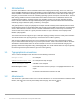
1 Introduction Our vision at Dell EMC is to be the essential infrastructure company from the edge, to the core, and to the cloud. Dell EMC Networking ensures modernization for today’s applications and for the emerging cloud-native world. Dell EMC is committed to disrupting the fundamental economics of the market with an open strategy that gives you the freedom of choice for networking operating systems and top-tier merchant silicon.
2 Hardware Overview This section briefly describes the hardware that is used to validate the deployment examples in this document. Appendix B contains a complete list of the hardware and software validated for this guide. Note: While the steps in this document were validated using the specified Dell EMC PowerSwitch models, they may be leveraged for other Dell EMC PowerSwitch models utilizing the same networking OS version or later assuming the switch has the available port numbers, speeds, and types.
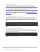
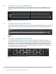
2.3 Dell EMC PowerSwitch Z9264F-ON The Dell EMC PowerSwitch Z9264F-ON is a 2-RU, multilayer switch with sixty-four 100GbE ports, or up to 128 10/25/40/50GbE ports using supported breakout cables. This guide uses two Z9264F-ONs as spine switches. Dell EMC PowerSwitch Z9264F-ON 2.4 Dell EMC PowerSwitch S3048-ON The Dell EMC PowerSwitch S3048-ON is a 1-RU switch with forty-eight 1GbE BASE-T ports and four 10GbE SFP+ ports.
3 BGP EVPN VXLAN overview EVPN is a control plane for VXLAN that is used to reduce flooding in the network and resolve scalability concerns. EVPN uses multiprotocol BGP (MP-BGP) to exchange information between VXLAN tunnel endpoints (VTEPs). EVPN was introduced in RFC 7432, and RFC 8365 describes VXLAN-based EVPN. VXLAN-based EVPN is a next-generation VPN. It is intended to replace previous generation VPNs like Virtual Private LAN Service (VPLS).
3.1 The VXLAN protocol VXLAN allows a Layer 2 network to scale across the data center by overlaying an existing Layer 3 network and is described in Internet Engineering Task Force document RFC 7348. Each overlay is referred to as a VXLAN segment. Each segment is identified through a 24-bit segment ID referred to as a VNI. This allows up to 16 Million VNIs, far more than the traditional 4,094 VLAN IDs allowed on a physical switch.
3.2 BGP EVPN VXLAN operation EVPN uses BGP to exchange endpoint MAC and IP address information between VTEPs. When a host sends a packet to an endpoint, the switch looks up the routing table for a match. If it finds a match that exists behind another VTEP, the packet is encapsulated with VXLAN and UDP headers and encapsulated again with outer IP and Ethernet headers for transport over the leaf-spine network.
4 Topology 4.1 Leaf-spine underlay This deployment uses a Layer 3 leaf-spine topology for the network underlay. The underlay provides transit for the virtual network overlays. In a Layer 3 leaf-spine network, traffic between leafs and spines is routed. Equal cost multi-path routing (ECMP) is used to load balance traffic across the Layer 3 connections. BGP is used to exchange routes. The Layer 3/Layer 2 (L3/L2) boundary is at the leaf switches.
4.1.1 BGP ASNs and router IDs Figure 9 shows the autonomous system numbers (ASNs) and router IDs used for the leaf and spine switches in this guide. Spine switches share a common ASN and each pair of leaf switches shares a common ASN. ASNs should follow a logical pattern for ease of administration and allow for growth as switches are added. Using private ASNs in the data center is a best practice. Private, 2-byte ASNs range from 64512 through 65534.
Each link is a separate, point-to-point IP network. Table 1 details the links labeled in Figure 10. The IP addresses in the table are used in the switch configuration examples. Point-to-point network IP addresses Link label Source switch Source IP address Destination switch Destination IP address Network A Spine 1 192.168.1.0 Leaf 1a 192.168.1.1 192.168.1.0/31 B Spine 2 192.168.2.0 Leaf 1a 192.168.2.1 192.168.2.0/31 C Spine 1 192.168.1.2 Leaf 1b 192.168.1.3 192.168.1.
4.2 Underlay network connections The physical underlay network connections are shown in Figure 11. Each leaf has one connection to each spine. 100GbE uplink ports on leafs are used to maximize bandwidth. Each host has one connection to each leaf configured as an LACP port channel on the host and as a VLT port channel on the two leafs. Connections from hosts to S5248F-ON leaf switches are 25GbE. Connections from hosts to S4148U-ON leaf switches are 10GbE (not shown).
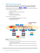
4.3 BGP EVPN VXLAN overlay Z9264F-1 VRF tenant1 VNI 1615 VNI 1614 VNI 1616 eBGP ECMP eBGP VTEP 10.222.222.1 S5248F-1a Z9264F-2 VLTi VTEP 10.222.222.2 S5248F-1b S4148U-2a VLTi 172.16.14.253 172.16.14.253 VNI 1614 172.16.15.253 172.16.15.253 VLT VLT VTEP 10.222.222.3 S4148U-2b S4148U-3a VLTi Border leafs VLT VM R740xd-1 VM VM R740xd-3 VM 172.16.16.253 VM R740xd-2 VM VM R740xd-4 VM Gateway/ Firewall Rack 1 Rack 2 VM VM on VNI 1614, IP 172.16.14.x /24 172.16.15.
4.4 OOB management network connections The OOB management network is an isolated network for remote management of servers, switches, and other devices. It is also used to carry heartbeat messages sent between leaf switches configured as VLT peers. Dell EMC recommends using at least one S3048-ON switch per 42-RU rack for OOB management network connections. Each S3048-ON has forty-eight 1GbE Base-T ports for connections to server iDRACs and switch management ports.
Four 10GbE SFP+ ports are available on the S3048-ON for uplinks to the OOB management network core (links not shown). Note: When running OS10EE, the S3048-ON will function as an OOB management switch with its factory default settings, or it may be configured as needed for your environment. By default, all ports are in switchport mode, in VLAN 1, administratively up, and rapid per-VLAN spanning tree plus (RPVST+) is enabled.
5 Switch preparation 5.1 Check switch OS version Dell EMC PowerSwitches must be running OS10EE version 10.4.3.1 or later for this deployment. Run the show version command to check the OS version. Dell EMC recommends upgrading to the latest release available on Dell Digital Locker (account required). OS10# show version Dell EMC Networking OS10-Enterprise Copyright (c) 1999-2019 by Dell Inc. All Rights Reserved. OS Version: 10.4.3.1 Build Version: 10.4.3.1.
5.3 Factory default configuration The switch configuration commands in the chapters that follow begin with the leaf switches at their factory default settings. Dell EMC PowerSwitches running OS10EE can be reset to their default configuration as follows: OS10# delete startup-configuration Proceed to delete startup-configuration [confirm yes/no(default)]:y OS10# reload System configuration has been modified.
6 Configure leaf switches Note: This deployment uses six leaf switches. All six leaf switch configuration files are provided as annotated text file attachments to this .pdf. Section 1.2 describes how to access .pdf attachments. This chapter details the configuration commands issued to the first two leaf switches, Leaf1a and Leaf1b. Configuration differences for Leafs 2a, 2b, 3a, and 3b are noted below the command tables. The commands should be entered in the order shown.
Leaf1a Leaf1b exit exit Note: The remaining leaf switches are configured in the same manner. 6.2 VLT configuration 1. Give the two interfaces used in the VLTi a description and remove them from Layer 2 mode with the no switchport command. 2. Create the VLT domain. Use the same value on both peers. 3. Add the backup destination address. This is the management IP address of the VLT peer switch. 4. Set the VLT delay restore timer to 120.
d. Configure a Route Target (RT). This example uses the format evi:evi and the route target type, import/export/both, is set to both. 5. For each VNI, 1614-1616, configure a virtual network interface as follows: a. Assign each to VRF tenant1. b. Configure each with an IP address. 6. A virtual router IP address if configured on VNI 1614 and VNI 1615 only. In this example, VNI 1616 uses an indirect gateway and does not use a virtual router address. 7.
Leaf1a Leaf1b ip virtual-router address 172.16.15.253 ip virtual-router address 172.16.15.253 interface virtual-network 1616 ip vrf forwarding tenant1 ip address 172.16.16.241/24 exit interface virtual-network 1616 ip vrf forwarding tenant1 ip address 172.16.16.
6.5 Downstream interface configuration Each downstream (server-connected) interface is configured as follows. 1. Create server-connected port channels. In this example, port channel 100 is connected to Server 1, and port channel 101 is connected to Server 2. a. Give the port channel a description. b. Use the switchport mode trunk command to enable the port channel to carry traffic for multiple VLANs. c. Allow tagged VLANs 1614 through 1616 on the trunked port channel. d.
6.6 Upstream interface configuration Each upstream (spine-connected) interface is configured as follows: 1. Provide an interface description. 2. Put each interface into Layer 3 mode by running the no switchport command and assigning an IP address per Table 1. 3. Set the MTU to 9216 bytes to allow jumbo frames. Upstream interfaces Leaf1a Leaf1b interface ethernet 1/1/53 description "Spine1 eth 1/1/1" no switchport ip address 192.168.1.
Route map configuration Leaf1a Leaf1b route-map spine-leaf permit 10 match ip address prefix-list spineleaf route-map spine-leaf permit 10 match ip address prefix-list spineleaf ip prefix-list spine-leaf seq 20 permit 10.2.2.0/24 ge 32 ip prefix-list spine-leaf seq 30 permit 10.222.222.0/24 ge 32 ip prefix-list spine-leaf seq 20 permit 10.2.2.0/24 ge 32 ip prefix-list spine-leaf seq 30 permit 10.222.222.
6.9 BGP configuration Note: AS and router ID numbers used in this section are from Figure 9. IP addresses are from Table 1. 1. 2. 3. 4. 5. 6. 7. Start BGP configuration with the router bgp AS_number command. Enable BFD, specify BFD timers, and enable the BFD active role. Specify to redistribute loopback routes into BGP for the IPv4 unicast address family. Enable ECMP with the bestpath as-path multipath-relax command.
Leaf1a Leaf1b no shutdown no shutdown neighbor 192.168.2.0 advertisement-interval 5 bfd fall-over remote-as 65101 address-family ipv4 unicast no shutdown neighbor 192.168.2.2 advertisement-interval 5 bfd fall-over remote-as 65101 address-family ipv4 unicast no shutdown neighbor 10.2.1.1 ebgp-multihop 2 remote-as 65101 send-community extended update-source loopback1 no shutdown neighbor 10.2.1.
6.10 Static route configuration 1. A default static route which points to the gateway/firewall switch is configured on all leaf switches so that VMs on VNIs 1614 and 1615 can access the Internet. 2. When the configuration is complete, exit configuration mode and save the configuration with the end and write memory commands. Note: Static routes to VNIs 1614 and 1615 are also configured on the gateway/firewall switch, so it can properly route return traffic to the VMs.
7 Configure spine switches This chapter details the configuration commands issued to the two Z9264F-ON spine switches, Spine1 and Spine2. The switches start at their factory default settings per Section 5.3. The commands in the sections that follow should be entered in the order shown. Note: Both spine switch configuration files are provided as text file attachments to this .pdf. Section 1.2 describes how to access .pdf attachments.
2. Configure a loopback interface to be used as the BGP router ID and IP address for BGP EVPN peering per Figure 9. Downstream interfaces 32 Spine1 Spine2 interface ethernet 1/1/1 description "Leaf1a eth 1/1/53" no switchport ip address 192.168.1.0/31 mtu 9216 no shutdown interface ethernet 1/1/1 description "Leaf1a eth 1/1/54" no switchport ip address 192.168.2.0/31 mtu 9216 no shutdown interface ethernet 1/1/2 description "Leaf1b eth 1/1/53" no switchport ip address 192.168.1.
7.3 Route map configuration In this section, a route map is configured to redistribute loopback addresses used as router IDs via BGP. 1. Configure a route map named spine-leaf. 2. Set the route map to match the IP prefix list items named spine-leaf. 3. Configure an IP prefix list that specifies 10.2.1.0/24 ge 32 to include all addresses in the 10.2.1.0/24 address range with a mask greater than or equal to 32. This range includes the spine router IDs. Route map configuration 7.
9. When the configuration is complete, exit configuration mode and save the configuration with the end and write memory commands.
Spine1 Spine2 no shutdown no shutdown neighbor 192.168.1.11 advertisement-interval 5 bfd fall-over remote-as 65203 address-family ipv4 unicast no shutdown neighbor 192.168.2.11 advertisement-interval 5 bfd fall-over remote-as 65203 address-family ipv4 unicast no shutdown neighbor 10.2.2.1 ebgp-multihop 2 remote-as 65201 send-community extended update-source loopback1 no shutdown neighbor 10.2.2.
Spine1 Spine2 address-family ipv4 unicast no activate address-family ipv4 unicast no activate address-family l2vpn evpn activate address-family l2vpn evpn activate neighbor 10.2.2.5 ebgp-multihop 2 remote-as 65203 send-community extended update-source loopback1 no shutdown neighbor 10.2.2.
8 Leaf switch validation After connected devices are configured, many commands are available to validate the network configuration. This section provides a list of common commands and their output for this topology. Note: The commands and output shown below are for Leaf1a. The output for the other leaf switches is similar. 8.1 General commands 8.1.
8.1.3 show lldp neighbors The show lldp neighbors command is useful for identifying connected switches by port. The items listed as Not Advertised are the server network adapters.
8.2 VLT validation commands 8.2.1 show vlt domain_id VLT configuration is verified by running the show vlt domain_id command on each of the leaf switches. The Role of one switch in the VLT pair is primary, and its peer switch (not shown) is assigned the secondary role. The VLTi link status and VLT Peer Status must both be up.
No mismatch VLT VLAN mismatch: No mismatch VLT Virtual Network Mismatch: Virtual Network Name Mismatch: No mismatch Virtual Network VLTi-VLAN Mismatch: No mismatch Virtual Network Mode Mismatch: No mismatch Virtual Network Tagged Interfaces Mismatch: No mismatch Virtual Network Untagged Interfaces Mismatch: No mismatch Virtual Network VNI Mismatch: No mismatch Virtual Network Remote-VTEP Mismatch: No mismatch Virtual Network anycast ip Mismatch: No mismatch Virtual Network anycast mac Mismatch: No mismatch
8.3 Routing validation commands 8.3.1 show bfd neighbors The show bfd neighbors command shows BFD session information. Leaf1a# show bfd neighbors * - Active session role -------------------------------------------------------------------------------LocalAddr RemoteAddr Interface State RxInt TxInt Mult VRF Clients -------------------------------------------------------------------------------* 10.2.2.1 10.2.1.1 loopback1 down 1000 1000 3 default bgp * 10.2.2.1 10.2.1.
8.3.3 show ip bgp summary The show ip bgp summary command shows summary BGP information regarding neighbor status and exchanged prefixes. Leaf1a# show ip bgp summary BGP router identifier 10.2.2.1 local AS number 65201 Global BFD is enabled Neighbor AS MsgRcvd MsgSent 192.168.1.0 65101 351 338 192.168.2.0 65101 346 340 192.168.3.1 65201 789 1271 8.4 EVPN validation commands 8.4.
EVI : 1616, State : up Bridge-Domain : Route-Distinguisher : Route-Targets : Inclusive Multicast : IRB : 8.4.3 Virtual-Network 1616, VNI 1616 1:10.222.222.1:1616 0:1616:1616 both 10.222.222.2, 10.222.222.3 Enabled(tenant1) show ip bgp l2vpn evpn summary The show ip bgp l2vpn evpn summary command displays summary information about BGP sessions using the EVPN address family. Leaf1a# show ip bgp l2vpn evpn summary BGP router identifier 10.2.2.
* Route distinguisher: 10.222.222.1:1614 VNI:1614 [2]:[0]:[48]:[e4:f0:04:81:40:98]:[0]:[0.0.0.0]/280 0 100 0 65101 65203 ? *>r Route distinguisher: 10.222.222.1:1615 VNI:1615 [2]:[0]:[48]:[00:50:56:bb:42:24]:[0]:[0.0.0.0]/280 0 100 32768 ? *>r Route distinguisher: 10.222.222.1:1615 VNI:1615 [2]:[0]:[48]:[00:50:56:bb:d0:77]:[0]:[0.0.0.0]/280 0 100 32768 ? *>r Route distinguisher: 10.222.222.1:1615 VNI:1615 [2]:[0]:[48]:[3c:2c:30:10:41:a3]:[0]:[0.0.0.0]/280 0 100 32768 ? *>r Route distinguisher: 10.222.222.
8.4.5 show evpn mac-ip The show evpn mac-ip command displays BGP Type 2 EVPN routes that include host MAC and IP addresses.
9 Spine switch validation After connected devices are configured, many commands are available to validate the network configuration. This section provides a list of the most common commands and their output for this topology. Note: The commands and output shown below are for Spine1. The output for Spine2 is similar. 9.1 General commands 9.1.
9.2 Routing validation commands 9.2.1 show bfd neighbors The show bfd neighbors command shows BFD session information. Spine1# show bfd neighbors * - Active session role -------------------------------------------------------------------------------LocalAddr RemoteAddr Interface State RxInt TxInt Mult VRF Clients -------------------------------------------------------------------------------* 10.2.1.1 10.2.2.1 loopback1 down 1000 1000 3 default bgp * 10.2.1.1 10.2.2.
C C C C C C 9.2.3 192.168.1.0/31 192.168.1.2/31 192.168.1.4/31 192.168.1.6/31 192.168.1.8/31 192.168.1.10/31 via via via via via via via 192.168.1.11 192.168.1.0 192.168.1.2 192.168.1.4 192.168.1.6 192.168.1.8 192.168.1.
10 VMware host and network configuration This example uses VMware ESXi VMs running on the four PowerEdge servers to validate the configuration. VMs are running a mix of Windows Server and Ubuntu Linux guest operating systems. This section shows how VMs are connected to the virtual networks configured in the preceding sections if ESXi and vCenter are used in the environment. 10.1 VMware ESXi download and installation Install VMware ESXi 6.7 Update 1 or later on each PowerEdge server.
10.4 Create VMs and install guest operating systems To create VMs and install supported guest operating systems on hosts running VMware ESXi, see vSphere 6.7 Virtual Machine Administration. In this deployment, each host has several VMs running a mix of Ubuntu Linux and Windows Server guest operating systems for testing. VMs created In this example, the name of each VM contains the VLAN/VNI it will be assigned to for clarity.
10.5 vSphere distributed switches A vSphere Distributed Switch, also referred to as a VDS or a distributed switch, is a virtual switch that provides network connectivity to hosts and virtual machines. Unlike vSphere standard switches, distributed switches act as a single switch across multiple hosts in a cluster. Distributed switches are configured in the vSphere Web Client, and the configuration is populated across all hosts associated with the switch.
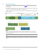
10.7 Add distributed port groups In this section, distributed port groups are created on the VDS. One port group is created for each VNI. To create the port groups: 1. In the vSphere Web Client, go to Home > Networking. 2. Right-click on Mgmt-VDS. Select Distributed Port Group > New Distributed Port Group. 3. On the Select name and location page, provide a name for the distributed port group to be associated with the first VNI configured on the leaf switches, e.g., VNI-1614-PG. Click Next. 4.
LAG configuration d. Click OK to close the dialog box. This creates lag1 on the VDS. The refresh icon ( lag to appear in the table as shown in Figure 18.
10.9 Associate hosts and assign uplinks to LAGs Note: Before starting this section, be sure you know the vmnic-to-physical adapter mapping for each host adapter port connected to the leaf switches. This can be determined by going to Home > Hosts and Clusters and selecting the host in the Navigator pane. In the center pane, select Configure > Networking > Physical adapters. Vmnic numbering will vary depending on adapters installed in the host. To add hosts and LAGs to the VDS: 1.
When complete, the Configure > Settings > Topology page for Mgmt-VDS appears as shown in Figure 19. LAGs configured on Mgmt-VDS This configuration brings up the VLT port channels on the leaf switches. This is confirmed by running the show vlt domain_id vlt-port-detail command on the leafs. The example below is from Leaf1a. The status for port channels connected to configured hosts is now up as shown in bold below.
10.10 Connect VMs to VDS and port group In this example, VM network adapters are associated with the VDS and applicable port group. 1. 2. 3. 4. Go to Home > Hosts and Clusters. Right click on a VM, VM-1614-1 in this example, and select Edit Settings. Next to Network adapter 1, select on the drop-down arrow and select Show more networks. Select the applicable port group and VDS from the list. In this case, VNI-1614-PG on Mgmt-VDS is selected as shown: Port group and VDS selected 5.
10.11 Configure networking in the guest OS For each VM attached to a virtual network, IP addresses and gateways are configured in the guest operating system per Table 16. Note: The VLAN/VNI column is shown for reference and does not need to be configured in the guest OS. The VLAN ID is configured in the distributed port group assigned to the virtual network adapter. VLANs are associated with corresponding VNIs on the leaf switches.
11 Validate connectivity The switches in this guide were configured to allow all VMs to communicate with each other and the external network. In this section, connectivity is tested between VMs on the same and different VNIs. Tunneled Layer 2 bridging, routing via anycast gateways, and routing via the indirect gateway are demonstrated. Note: Guest operating system firewalls may need to be temporarily disabled or modified to allow responses to ICMP ping requests.
Packet capture showing successful tunneled Layer 2 ping The first red box shows the source and destination are the VTEPs for Rack 1 and Rack 2 respectively. The second red box shows the packet is encapsulated with VXLAN on VNI 1614. The third red box shows the source and destination IP addresses of the VMs. 11.2 Validate routing using anycast gateways This test is between two VMs on different VNIs on different leaf pairs. In this example, VM-1614-1 pings VM1615-3.
because routing occurs on ingress with asymmetric IRB. This means that packets travel to their destination on the destination VNI, which is 1615 in this case. The third red box shows the source and destination IP addresses of the VMs. 11.3 Validate routing using the indirect gateway Two tests are run in this section. In the first test, a VM that has its default gateway set to the indirect gateway pings the loopback interface on the Gateway/Firewall switch, 1.1.1.
Packet capture showing successful ping between a VM-1615-3 and VM-1616-1 The above capture was taken from a leaf-spine link in Rack 2. The first red box shows the source VTEP is from Rack 3 and the destination VTEP is in Rack 2. The second red box shows the packet is encapsulated with VXLAN on VNI 1615. This is because and packets travel to their destination on the destination VNI with asymmetric IRB. The third red box shows the source and destination IP addresses.
A Gateway/firewall switch configuration This section details the configuration of an S4112F-ON switch used as the external gateway/simulated firewall to validate this deployment example. This switch is connected to the border leafs, Leaf3a and Leaf3b, as shown in Figure 12. A.1 Initial configuration settings 1. 2. 3. 4. Enter configuration mode with the configure terminal command. Configure the hostname. If DHCP is not used, configure the OOB management IP address and default gateway.
A.3 Simulated external network interface configuration 1. Create a loopback interface. 2. Specify an IP address to represent a connection to the external network. Loopback interface configuration Gateway/firewall switch interface loopback0 description testlo0 no shutdown ip address 1.1.1.1/32 A.4 Upstream interfaces These interfaces are connected to the border leafs upstream. 1. Create a port channel and assign it to VLAN 1. 2. Assign the interfaces connected to the border leafs to the port channel.
B Validated components The following tables include the hardware, software, and firmware used to configure and validate the examples in this guide. B.1 Dell EMC PowerSwitches Switches and OS versions Qty Item OS Version 2 Dell EMC PowerSwitch S5248F-ON leaf switch 10.4.3.1.154 4 Dell EMC PowerSwitch S4148U-ON leaf switch 10.4.3.1.154 2 Dell EMC PowerSwitch Z9264-ON spine switch 10.4.3.1.154 1 Dell EMC PowerSwitch S3048-ON management switch 10.4.3.1.
C Technical resources C.1 Dell EMC product manuals and technical guides Dell EMC Networking Guides OS10 Enterprise Edition User Guide Release 10.4.3.
D Fabric Design Center The Dell EMC Fabric Design Center (FDC) is a cloud-based application that automates the planning, design, and deployment of network fabrics that power Dell EMC compute, storage and hyper-converged infrastructure solutions. The FDC is ideal for turnkey solutions and automation based on validated deployment guides. FDC allows design customization and flexibility to go beyond validated deployment guides. For additional information, visit the Dell EMC Fabric Design Center.
E Support and feedback Contacting Technical Support Support Contact Information Web: http://www.dell.com/support Telephone: USA: 1-800-945-3355 Feedback for this document We encourage readers to provide feedback on the quality and usefulness of this publication by sending an email to Dell_Networking_Solutions@Dell.com.