Dell EMC PowerSwitch S3048-ON Installation Guide June 2021 June 2021 Rev.
Notes, Cautions, and Warnings NOTE: A NOTE indicates important information that helps you make better use of your computer. CAUTION: A CAUTION indicates either potential damage to hardware or loss of data and tells you how to avoid the problem. NOTE: A WARNING indicates a potential for property damage, personal injury, or death. © 2014 - 2021 Dell Inc. or its subsidiaries. All rights reserved. Dell, EMC, and other trademarks are trademarks of Dell Inc. or its subsidiaries.
Contents Chapter 1: About this guide........................................................................................................... 5 Related documents............................................................................................................................................................. 5 Chapter 2: The S3048–ON switch................................................................................................. 6 Introduction...............................................
Fan module installation.....................................................................................................................................................26 Fan module replacement................................................................................................................................................. 26 After installing the switch...........................................................................................................................................
1 About this guide This guide provides site preparation recommendations, step-by-step procedures for rack mounting and desk mounting, inserting optional modules, and connecting to a power source. CAUTION: To avoid electrostatic discharge (ESD) damage, wear grounding wrist straps when handling this equipment. NOTE: Only trained and qualified personnel can install this equipment. Read this guide before you install and power up this equipment. This equipment contains two power cords.
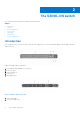
2 The S3048–ON switch The following sections describe the Dell EMC S3048–ON switch. Topics: • • • • • • • Introduction Features Physical dimensions Switch status LED display Prerequisites Switch configurations Introduction The S3048-ON is a low-cost top-of-rack (ToR) switch for 1 Gbps links to servers and 10 Gbps uplinks to the 40 Gbps switching fabric in the core. Figure 2. S3048–ON I/O-side view 1. 2. 3. 4. 5. Forty-eight 10/100/1000BAse-T RJ-45 ports Four SFP+ ports Serial console port USB 2.
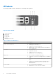
Features The S3048–ON offers the following features. ● ● ● ● ● ● ● ● ● ● ● ● ● Forty-eight 10/100/1000Base-T RJ-45 ports Four SFP+ 10G ports One serial console port One universal serial bus 2.0 (USB Type-A) port for additional file storage One management port Rangeley Central processing unit (CPU) system with 2GB DDR III RAM.
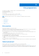
LED behavior The following S3048–ON switch LED behavior is seen during ONIE operations: Figure 4. S3048–ON LEDs 1. 2. 3. 4. 5. 6. System Status LED Master LED Power LED Locator LED Fan LED Management Port LEDs Table 1.
Table 2. Management Ethernet port LEDs LED Description Link LED ● Off—No link ● Solid green—Link on 1 Gbps speed ● Solid yellow—Link on 10/100 Mbps speeds Table 3.
3 Site preparations The S3048–ON is suitable for installation as part of a common bond network (CBN). You can install the switch in: ● Network telecommunication facilities ● Data centers ● Other locations where the National Electric Code (NEC) applies For more information about S3048–ON specifications, see Specifications. NOTE: Install the S3048–ON switch into a rack or cabinet before installing any optional components.
Rack mounting When you prepare your equipment rack, ensure that the rack is grounded. Ground the equipment rack to the same ground point the power service in your area uses. The ground path must be permanent. Switch ground Dell EMC recommends you ground your switch. Use the S3048–ON in a common bond network (CBN). Connect the grounding cables as described in Install the S3048–ON. Fans and airflow The S3048–ON fans support two airflow options—normal and reverse.
NOTE: ESD damage can occur when components are mishandled. Always wear an ESD-preventive wrist or heel ground strap when handling the S3048–ON and its accessories. After you remove the original packaging, place the S3048–ON and its components on an anti-static surface.
4 NEBS compliance For your switch to be network equipment building system (NEBS) compliant, you must follow the instructions detailed in this section. To be NEBS compliant, orient your switch in the rack so that the air inlet is from the front aisle and the air exhaust is to the rear aisle.
5 Install the S3048–ON To install the S3048–ON switch, complete the installation procedures in the order presented in this chapter. Always handle the S3048–ON and its components with care. Avoid dropping the switch or its field replaceable units (FRUs). This chapter describes the installation procedures as follows: 1. 2. 3. 4. 5. Unpack Rack or cabinet hardware installation Switch installation Optics installation Power up the switch NOTE: ESD damage can occur if components are mishandled.
Rack or cabinet hardware installation You may either place the switch on a rack shelf or mount the switch directly into a 19" wide, EIA-310- E-compliant rack— four-post, two-post, or threaded methods. The Dell EMC ReadyRails™ system is provided for 1U front-rack and two-post installations. The ReadyRails system includes two separately packaged rail assemblies and two rails that are shipped attached to the sides of the switch. WARNING: This is a condensed reference.
Figure 5. 1U tool-less configuration 2. Align and seat the front flange pegs in the holes on the front side of the vertical post, item 2. 3. Repeat this procedure for the second rail. 4. To remove each rail, pull on the latch release button on each flange ear and unseat each rail, item 3. Two-post flush-mount installation 1. For this configuration, remove the castings from the front side of each ReadyRails assembly, item 1.
3. Slide the plunger bracket forward against the vertical post and secure the plunger bracket to the post flange with two user-supplied screws. item 3. 4. Repeat this procedure for the second rail. Two-post center-mount installation 1. Slide the plunger bracket rearward until it clicks into place and secure the bracket to the front post flange with two user-supplied screws, item 1. Figure 7. Two-post center-mount configuration 2. Slide the back bracket towards the post.
Figure 8. Four-post threaded configuration 2. For each rail, attach the front and rear flanges to the post flanges with two user-supplied screws at each end, item 2. Switch installation You can mount the switch in the 1U front-rack or 1U flush or center two-post configurations. The following is an example of a front-rack configuration: For the 1U flush or center two-post configurations, slide the switch into the rails in the same manner as the four-post configurations.
Figure 9. Switch rails attachment 2. After you have installed both switch rails, line them up on the previously mounted Ready-Rails and slide the switch in until it is flush with front of rack. About three inches before you fully insert your switch, the rail locking feature engages to keep the switch from inadvertently sliding out of the rack and falling. Figure 10. Front rack installation NOTE: Do not the use the mounted ReadyRails as a shelf or a workplace.
Ground cable Dell EMC recommends you ground your switch. To attach the ground cable to the chassis, use a single M4x0.7 screw. The cable itself is not included with the S3048–ON switch. To properly ground the chassis, Dell EMC recommends using a 6 AWG one-hole lug, #10 hole size, 63" spacing, not included in shipping. The one-hole lug must be a UL recognized, crimp-type lug. CAUTION: Grounding conductors must be made of copper. Do not use aluminum conductors.
● The ambient temperature around the unit, which may be higher than the room temperature, is within the limits specified for the S3048–ON. For more information, see Specifications. ● There is sufficient airflow around the unit. ● The input circuits are correctly sized for the loads and that you use sufficient overcurrent protection devices. ● All protective covers are in place. ● Blank panels are installed if you do not install optional modules.
6 Power supplies The S3048–ON ships with one AC power supply. Dell EMC recommends purchasing a second power supply. The S3048–ON supports AC power supplies with two air-flow directions—from the I/O side to the PSU side and from the PSU side to the I/O side. Two PSUs are required for full redundancy, but the switch can operate with a single PSU. The PSUs are field replaceable.
NOTE: To comply with the GR-1089 Lightning Criteria for Equipment Interfacing with AC Power Ports, use an external surge protection device (SPD) at the AC input of the router. AC power supply installation NOTE: The PSU slides into the slot smoothly. Do not force a PSU into a slot as this action may damage the PSU or the S3048–ON chassis. NOTE: Ensure that you correctly install the PSU. When you install the PSU correctly, the power connector is on the right side of the PSU.
AC power supply replacement CAUTION: Disconnect the power cord before removing the power supplies. Also, disconnect all power cords before servicing. NOTE: The PSU slides into the slot smoothly. Do not force a PSU into a slot as this action may damage the PSU or the S3048–ON chassis. NOTE: If a PSU fails, you must replace the entire unit. There are no field serviceable components in the PSU. NOTE: If you use a single PSU, install a blank plate in the other PSU slot.
7 Fans The S3048–ON comes from the factory with one PSU and three fan modules installed in the chassis. The fan modules and the power supplies, which have integrated fans, are hot-swappable. NOTE: To run the switch, all slots must have operating fan units. If you do not install a module in each slot either as part of the PSU or as an independent fan module, the switch shuts down in one minute. In addition to the power supply modules, you can order and install fan modules separately.
Fan module installation The fan modules in the S3048–ON are field replaceable. Module slot 1 is on the left side of the chassis, module slot 2 is in the middle of the chassis, and module slot 3 is on the right side of the chassis. CAUTION: DO NOT mix airflow directions. All fans must use the same airflow direction—reverse or normal. If you mix the airflow direction, the switch detects the discrepancy and issues an alarm. You must correct the mixed airflow direction. 1.
8 Management ports Besides the 10/100/1000Base-T RJ-45 ports, the S3048–ON switch provides several ports for management and storage. Topics: • • • RS-232 console port access Before you install an OS ONIE service discovery RS-232 console port access The RS-232 console port is on the I/O-side of the S3048-ON chassis, as shown. Figure 14. S3048–ON RS-232 console ports 1. RS-232 Console Port, top 2.
USB storage mount The USB storage supports the FAT file system. The USB storage does not automatically mount. To use USB storage, you must first mount the device. 1. Create a mount directory for the USB. ONIE:/ # mkdir /mnt/usb 2. View the fixed disks using the fdisk command. ONIE:/mnt # fdisk -l For internal storage: Disk /dev/sda: 15.
| ONIE: Uninstall OS | | ONIE: Update ONIE | | ONIE: Embed ONIE | | ONIE: Diag ONIE | | Dell EMC DIAG | | | | | | | | | | | +----------------------------------------------+ Your switch comes with ONIE installed.
RX bytes:1152 (1.1 KiB) TX bytes:6864 (6.7 KiB) Interrupt:21 Memory:ff300000-ff320000 To assign an IP address to the management interface, eth0, and verify network connectivity, use the ifconfig eth0 command, as shown. ONIE:/ # ifconfig eth0 10.11.53.33/16 Verify the network connection with ping. ONIE:/ # ping 10.11.8.12 PING 10.11.8.12 (10.11.8.12): 56 data bytes 64 bytes from 10.11.8.12: seq=0 ttl=62 time=1.357 ms 64 bytes from 10.11.8.12: seq=1 ttl=62 time=0.
9 Specifications This chapter lists the S3048–ON specifications. CAUTION: Operate the product at an ambient temperature not higher than 113°F (45°C). CAUTION: Lithium Battery Caution: There is a danger of explosion if the battery is incorrectly replaced. Replace only with same or equivalent type of battery. Dispose of the batteries according to the manufacturer's instructions. NOTE: For RoHS information, see Restricted Material Compliance.
Table 5. Environmental parameters (continued) Parameter Specifications Maximum operational altitude 10,000 feet (3,048 meters) Maximum non-operational altitude No performance degradation to 35,000 feet (10,668 meters) Shock SV0115 — ODM Table 6. AC power requirements Parameter Specifications Power Supply 100–240 VAC 50/60 Hz Maximum Current Draw Per System 3A @ 100vac 2A @ 200vac PSU Maximum Power Capability 224.4 Watts PSU Maximum Power Capability, North America Only 424.
Figure 15. Canadian Department of Communication Statement European Union EMC Directive Conformance Statement This product is in conformity with the protection requirements of EU Council Directive 2004/108/EC on the approximation of the laws of the Member States relating to electromagnetic compatibility.
Figure 17. Japan Warning Label Korean Certification of Compliance Figure 18. Korean Certification of Compliance Figure 19. Korean Package Label Safety Standards and Compliance Agency Certifications ● CUS UL 60950-1, 2nd Edition ○ Meets or exceeds Hi Pot and Ground Continuity testing per UL 60950-1.
● IEC 60950-1, 2nd Ed, including all National Deviations and Group Differences Electromagnetic compatibility Emissions ● ● ● ● ● ● International: CISPR 22: 2006, Class A Australia/New Zealand: AS/NZS CISPR 22:2009, Class A Canada: ICES-003, Issue-4, Class A Europe: EN55022 2006 (CISPR 22: 2006), Class A Japan: VCCI V-3/2011.04 Class A USA: FCC CFR47 Part 15, Subpart B, Class A Immunity ● ● ● ● ● ● ● ● ● ● EN 300 386 v1.5.
customers for the return, recycling and recovery of WEEE. Customer participation is important to minimize any potential effects of EEE on the environment and human health due to the potential presence of hazardous substances in EEE. Dell EMC products, which fall within the scope of the WEEE, are labeled with the crossed-out wheelie-bin symbol, as shown above, as required by WEEE. For information on Dell EMC product recycling offerings, see the WEEE Recycling instructions on Support.
10 Dell EMC support The Dell EMC support site provides documents and tools to help you effectively use Dell EMC equipment and mitigate network outages. Through the support site you can obtain technical information, access software upgrades and patches, download available management software, and manage your open cases. The Dell EMC support site provides integrated, secure access to these services. To access the Dell EMC support site, go to www.dell.com/support/.