
Setup Guide
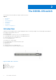

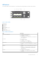
Table Of Contents
- Dell EMC PowerSwitch S4048-ON Installation Guide March 2021
- About this guide
- The S4048–ON switch
- Site preparations
- NEBS compliance
- S4048–ON installation
- Power supplies
- Fans
- Management ports
- Specifications
- Chassis physical design
- IEEE standards
- Agency compliance
- Network Equipment Building Systems Compliance
- USA Federal Communications Commission Statement
- European Union EMC Directive Conformance Statement
- Japan VCCI Compliance for Class A Equipment
- Korean Certification of Compliance
- Safety Standards and Compliance Agency Certifications
- Electromagnetic Compatibility
- Product recycling and disposal
- Technical Support

LED behavior
The following S4048–ON switch LED behavior is seen during open networking installation environment (ONIE) operations:
Figure 5. S4048–ON LEDs
1. Master LED
2. System LED
3. Power LED
4. Fan LED
5. Locator LED
6. SFP+ link/activity LEDs
7. Stack LED
8. USB port LED
9. QSFP+ link/activity LEDs
Table 1. S4048–ON LED behavior
LED Description
System Status/Health LED
● Solid green—Normal operation
● Flashing green—Booting
● Solid amber—Critical system error
● Flashing amber—Non-critical system error, fan failure, or
power supply failure
Power LED
● Off—No power
● Solid Green—Normal
● Solid amber—POST is in process
● Flashing amber—Power supply failed
MASTER LED
● Off—Switch is in Stacking Slave mode
● Solid green—System is in Stacking Master or Standalone
mode
FAN LED
● Solid green—fan powered and running at the expected
RPM
● Solid amber—fan failed including incompatible airflow
direction when you insert the PSU or fan trays with
differing airflows
PSU LED
● Solid green—Normal operation
● Solid amber—Power supply critical event causing a
shutdown
The S4048–ON switch 9