
Administrator Guide

If you delete the dot1p priority-priority group mapping (no priority pgid command) before you apply the new DCB map, the
default PFC and ETS parameters are applied on the interfaces. This change may create a DCB mismatch with peer DCB devices and
interrupt network operation.
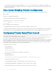
Data Center Bridging: Default Configuration
Before you configure PFC and ETS on a switch see the priority group setting taken into account the following default settings:
DCB is enabled.
PFC and ETS are globally enabled by default.
The default dot1p priority-queue assignments are applied as follows:
Dell(conf)#do show qos dot1p-queue-mapping
Dot1p Priority : 0 1 2 3 4 5 6 7
Queue : 0 0 0 1 2 3 3 3
Dell(conf)#
PFC is not applied on specific dot1p priorities.
ETS: Equal bandwidth is assigned to each port queue and each dot1p priority in a priority group.
To configure PFC and ETS parameters on an interface, you must specify the PFC mode, the ETS bandwidth allocation for a priority group,
and the 802.1p priority-to-priority group mapping in a DCB map. No default PFC and ETS settings are applied to Ethernet interfaces.
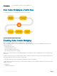
Configuring Priority-Based Flow Control
Priority-Based Flow Control (PFC) provides a flow control mechanism based on the 802.1p priorities in converged Ethernet traffic received
on an interface and is enabled by default when you enable DCB.
As an enhancement to the existing Ethernet pause mechanism, PFC stops traffic transmission for specified priorities (Class of Service
(CoS) values) without impacting other priority classes. Different traffic types are assigned to different priority classes.
When traffic congestion occurs, PFC sends a pause frame to a peer device with the CoS priority values of the traffic that is to be stopped.
Data Center Bridging Exchange protocol (DCBx) provides the link-level exchange of PFC parameters between peer devices. PFC allows
network administrators to create zero-loss links for Storage Area Network (SAN) traffic that requires no-drop service, while retaining
packet-drop congestion management for Local Area Network (LAN) traffic.
To configure PFC, follow these steps:
1 Create a DCB Map.
CONFIGURATION mode
dcb-map dcb-map-name
The dcb-map-name variable can have a maximum of 32 characters.
2 Create a PFC group.
CONFIGURATION mode
priority-group group-num {bandwidth bandwidth | strict-priority} pfc on
The range for priority group is from 0 to 7.
Set the bandwidth in percentage. The percentage range is from 1 to 100% in units of 1%.
Committed and peak bandwidth is in megabits per second. The range is from 0 to 40000.
Committed and peak burst size is in kilobytes. Default is 50. The range is from 0 to 10000.
254
Data Center Bridging (DCB)