VXLAN and BGP EVPN Configuration Guide for Dell EMC SmartFabric OS10 Release 10.5.
Notes, cautions, and warnings NOTE: A NOTE indicates important information that helps you make better use of your product. CAUTION: A CAUTION indicates either potential damage to hardware or loss of data and tells you how to avoid the problem. WARNING: A WARNING indicates a potential for property damage, personal injury, or death. © 2020 Dell Inc. or its subsidiaries. All rights reserved. Dell, EMC, and other trademarks are trademarks of Dell Inc. or its subsidiaries.
Contents 1 VXLAN ........................................................................................................................................ 6 VXLAN concepts................................................................................................................................................................... 7 VXLAN as NVO solution.......................................................................................................................................................
show mac address-table nve....................................................................................................................................... 33 show mac address-table virtual-network................................................................................................................... 34 Example: VXLAN with static VTEP................................................................................................................................... 34 2 BGP EVPN for VXLAN....
Assign interfaces to be managed by the controller................................................................................................. 160 Service Nodes............................................................................................................................................................... 161 View replicators............................................................................................................................................................
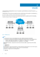
1 VXLAN A virtual extensible LAN (VXLAN) extends Layer 2 (L2) server connectivity over an underlying Layer 3 (L3) transport network in a virtualized data center. A virtualized data center consists of virtual machines (VMs) in a multi-tenant environment. OS10 supports VXLAN as described in RFC 7348. VXLAN provides a L2 overlay mechanism on an existing L3 network by encapsulating the L2 frames in L3 packets.
• Z9332F-ON Topics: • • • • • • • • • • VXLAN concepts VXLAN as NVO solution Configure VXLAN L3 VXLAN route scaling DHCP relay on VTEPs View VXLAN configuration VXLAN MAC addresses VXLAN commands VXLAN MAC commands Example: VXLAN with static VTEP VXLAN concepts Network virtualization overlay (NVO) An overlay network extends L2 connectivity between server virtual machines (VMs) in a tenant segment over an underlay L3 IP network.
• • You can map only one VLAN ID to a virtual network. Ideally suited for existing tenant VLANs that stretch over an IP fabric using VXLAN. Port-scoped VLAN A Port,VLAN pair that maps to a virtual network ID (VNID) in OS10. Assign an individual member interface to a virtual network either with an associated tagged VLAN or as an untagged member. Using a port-scoped VLAN, you can configure: • • The same VLAN ID on different access interfaces to different virtual networks.
3. Return to CONFIGURATION mode. exit 4. Enter NVE mode from CONFIGURATION mode. NVE mode allows you to configure the VXLAN tunnel endpoint on the switch. nve 5. Configure the Loopback interface as the source tunnel endpoint for all virtual networks on the switch in NVE mode. source-interface loopback number 6. Return to CONFIGURATION mode. exit Configure a VXLAN virtual network To create a VXLAN, assign a VXLAN segment ID (VNI) to a virtual network ID (VNID) and configure a remote VTEP.
2. Configure port interfaces as trunk members of the VLAN in Interface mode. interface ethernet node/slot/port[:subport] switchport mode trunk switchport trunk allowed-vlan vlan-id exit The local physical ports assigned to the VLAN transmit packets over the virtual network. NOTE: A switch-scoped VLAN assigned to a virtual network cannot have a configured IP address and cannot participate in L3 routing; for example: OS10(config)# interface vlan 102 OS10(conf-if-vlan-102)# ip address 1.1.1.
1. Create a reserved VLAN ID to assign untagged traffic on member interfaces to a virtual network in CONFIGURATION mode. The VLAN ID is used internally for all untagged member interfaces on the switch that belong to virtual networks. virtual-network untagged-vlan untagged-vlan-id 2. Configure port interfaces as trunk members and remove the access VLAN in Interface mode. interface ethernet node/slot/port[:subport] switchport mode trunk no switchport access vlan exit 3.
The interface IP address must be unique on each VTEP, including VTEPs in VLT pairs. You can configure an IPv6 address on the virtual-network interface. Different virtual-network interfaces you configure on the same VTEP must have virtual-network IP addresses in different subnets. If you do not assign the virtual-network interface to a tenant VRF, it is assigned to the default VRF. interface virtual-network vn-id ip vrf forwarding tenant-vrf-name ip address ip-address/mask no shutdown exit 4.
Virtual network VNID 13 • VTEP Anycast gateway MAC address VTEP 3 00.11.22.33.44.55 VTEP 1 00.11.22.33.44.55 VTEP 2 00.11.22.33.44.55 VTEP 3 00.11.22.33.44.55 Configure a unique IP address on the virtual-network interface on each VTEP across all virtual networks. Configure the same anycast gateway IP address on all VTEPs in a virtual-network subnet. For example: Table 2.
• • If you use a port-scoped VLAN to assign tagged access interfaces to a virtual network, to identify traffic belonging to each virtual network, you must configure a unique VLAN ID for the VLT Interconnect (VLTi) link. Configure a VLAN to transmit VXLAN traffic over the VLTi link in VIRTUAL-NETWORK mode. All traffic sent and received from a virtual network on the VLTi carries the VLTi VLAN ID tag. Configure the same VLTi VLAN ID on both VLT peers.
OS10 Switch Overlay nexthop entries Underlay nexthop entries Overlay L3 RIF entries Underlay L3 RIF entries S52xx-ON series: — — — — default-overlay-routing 8192 57344 2048 14336 disable-overlay-routing 0 65536 0 16384 balanced-overlay-routing 32768 32768 8192 8192 scaled-overlay-routing 53248 12288 12288 4096 S4248-ON: — — — — default-overlay-routing 20480 110592 4096 28672 NOTE: The S4248-ON switch supports only one default profile to reserve resources for overlay A
Similarly, the DHCP server in the underlay VRF must be reachable from the client tenant VRF in the overlay. Configure a static route for the DHCP server subnet in the underlay default VRF, and leak the static route to the client tenant VRF in the overlay. This configuration sets up a bi-directional communication between the client and DHCP server across the virtual networks. The route-leaking configuration is not required if the VxLAN overlay subnet and underlay subnet are in same default VRF.
View the VXLAN virtual-network statistics OS10# show virtual-network counters Virtual-Network Input (Packets/Bytes) 1000 857/8570 2000 457/3570 Output (Packets/Bytes) 257/23709 277/13709 OS10# show virtual-network counters interface 1/1/3 vlan 100 Virtual-Network Input (Packets/Bytes) Output (Packets/Bytes) 1000 857/8570 257/23709 2000 457/3570 277/13709 NOTE: Using flex counters, OS10 may display additional packets in the Output field number, but the additional packets do not transmit.
B - BGP, IN - internal BGP, EX - external BGP O - OSPF, IA - OSPF inter area, N1 - OSPF NSSA external type 1, N2 - OSPF NSSA external type 2, E1 - OSPF external type 1, E2 - OSPF external type 2, * - candidate default, + - summary route, > - non-active route Gateway of last resort is not set Destination Gateway Dist/Metric Last Change ------------------------------------------------------------------------C 100.1.0.0/16 via 100.1.1.4 virtual-network60000 0/0 00:36:24 C 100.33.0.0/16 via 100.33.1.
Command Description show mac address-table extended [address macaddress | interface {ethernet node/slot/ port:subport | port-channel number} | static | dynamic] Displays MAC addresses learned on all VLANs and VXLANs (default). address mac-address: Displays only information about the specified MAC address. interface ethernet node/slot/port:subport: Displays only MAC addresses learned on the specified interface.
Table 5. Clear VXLAN MAC addresses Command Description clear mac address-table dynamic virtual-network Clears all MAC addresses learned on all VXLAN virtual [interface {ethernet node/slot/port:subport | networks. port-channel number} | local | vn-id [address macinterface ethernet node/slot/port:subport: address | local]] Clears only MAC addresses learned on the specified interface. interface port-channel number: Clears only MAC addresses learned on the specified port channel.
Supported releases 10.4.3.0 or later interface virtual-network Configures a virtual-network router interface. Syntax Parameters interface virtual-network vn-id virtualnetwork vn-id Default Not configured Command mode CONFIGURATION Enter a virtual-network ID, from 1 to 65535. Usage information Configure a virtual-network router interface to enable hosts connected to a virtual network to route traffic to hosts on another virtual network in the same VRF.
Command mode CONFIGURATION Usage information Configure the same MAC address on all VTEPs so that the anycast gateway MAC address remains the same if a VM migrates to a different VTEP. Because the configured MAC address is automatically used for all VXLAN virtual networks, configure it in global Configuration mode. Example Supported releases OS10(config)# ip virtual-router mac-address 00:01:01:01:01:01 10.4.3.
remote-vtep Configures the IP address of a remote tunnel endpoint in a VXLAN network. Syntax remote-vtep ip-address Parameters ip-address — Enter the IP address of a remote virtual tunnel endpoint (VTEP). Default Not configured Command mode VIRTUAL-NETWORK VXLAN-VNI Usage information After you configure the remote VTEP, the VXLAN virtual network is enabled to start sending server traffic. You can configure multiple remote VTEPs.
Parameters vn-id Default Not configured Command mode EXEC Enter a virtual-network ID, from 1 to 65535. Usage information Use this command to display the virtual-network IP address used for routing traffic in a virtual network. Traffic counters also display. Example Supported releases show interface virtual-network 102 Virtual-network 102 is up, line protocol is up Address is 14:18:77:25:6f:84, Current address is 14:18:77:25:6f:84 Interface index is 66 Internet address is 12.12.12.
show nve remote-vtep counters Displays VXLAN packet statistics for a remote VTEP. Syntax show nve remote-vtep [ip-address] counters Parameters • Default Not configured Command mode EXEC ip-address — Enter IP address of a remote VTEP. Usage information Use this command to display input and output statistics for VXLAN traffic on a remote VTEP. A VTEP is identified by its IP address. Use the clear nve remote-vtep [ip-address] counters command to clear VXLAN packet statistics.
Example Supported releases OS10# show virtual-network Codes: DP - MAC-learn Dataplane, CP - MAC-learn Controlplane, UUD - UnknownUnicast-Drop Un-tagged VLAN: 888 Virtual Network: 60000 VLTi-VLAN: 2500 Members: VLAN 1000: port-channel1, ethernet1/1/9, ethernet1/1/10 VLAN 2500: port-channel1000 VxLAN Virtual Network Identifier: 16775000 Source Interface: loopback100(222.222.222.222) Remote-VTEPs (flood-list): 55.55.55.55(DP),77.1.1.1(DP) 10.4.2.
member port or VLAN members of a virtual network, use the clear virtual-network interface {ethernet node/slot/port:subport | port-channel number} [vlan vlan-id] counters command. Example Supported releases OS10# show virtual-network interface 1/1/3 vlan 100 counters Virtual-Network Input (Packets/Bytes) Output (Packets/Bytes) 2000 457/3570 277/13709 10.4.2.0 or later show virtual-network interface Displays the VXLAN virtual networks and server VLANs where a port is assigned.
Supported releases 10.4.2.0 or later show vlan (virtual network) Displays the VLANs assigned to virtual networks. Syntax show vlan Parameters None Default Not configured Command mode EXEC Usage information Use this command to display the VLAN port interfaces that transmit VXLAN packets over a virtual network.
virtual-network Creates a virtual network for VXLAN tunneling. Syntax Parameters virtual-network vn-id vn-id Default Not configured Command mode CONFIGURATION Enter the virtual-network ID, from 1 to 65535. Usage information The virtual network operates as a L2 bridging domain. To add a VXLAN to the virtual network, use the vxlanvni command. The no version of this command removes the configured virtual network. Example Supported releases OS10(config)# virtual-network 1000 OS10(config-vn)# 10.4.2.
VXLAN MAC commands clear mac address-table dynamic nve remote-vtep Clears all MAC addresses learned from a remote VTEP. Syntax clear mac address-table dynamic nve remote-vtep ip-address Parameters remote-vtep ip-address Default Not configured Command mode EXEC Clear MAC addresses learned from the specified remote VTEP. Usage information To display the MAC addresses learned from a remote VTEP, use the show mac address-table nve remote-vtep command.
Supported releases 10.4.2.0 or later show mac address-table count extended Displays the number of MAC addresses learned on all VLANs and VXLAN virtual networks. Syntax Parameters show mac address-table count extended [interface {ethernet node/slot/ port:subport | port-channel number}] interface ethernet node/ slot/ port[:subport] Display the number of MAC addresses learned on all VLANs and VXLANs on the specified interface.
Static Address (User-defined) Count : Total MAC Addresses in Use: Supported releases 0 2 10.4.2.0 or later show mac address-table count virtual-network Displays the number of MAC addresses learned on virtual networks. Syntax show mac address-table count virtual-network [dynamic | local | remote | static | interface {ethernet node/slot/port:subport | port-channel number} | vn-id] Parameters dynamic Display the number of local dynamically-learned MAC addresses.
interface port-channel number Display only MAC addresses learned on the specified port channel. static Display only static MAC addresses. dynamic Display only dynamic MAC addresses. Default Not configured Command mode EXEC Usage information By default, MAC learning from a remote VTEP is enabled. Use this command to verify the MAC addresses learned both on VXLAN virtual networks and VLANs on the switch.
Supported releases 10.4.2.0 or later show mac address-table virtual-network Displays the MAC addresses learned on all or a specified virtual network. Syntax show mac address-table virtual-network [vn-id | local | remote | static | dynamic | address mac-address | interface {ethernet node/slot/port:subport | port-channel number}] Parameters vn-id Display only information about the specified virtual network. local Display only locally learned MAC addresses. remote Display only remote MAC addresses.
Figure 2. Static VXLAN use case VTEP 1 Leaf Switch 1. Configure the underlay OSPF protocol Do not configure the same IP address for the router ID and the source loopback interface in Step 2. OS10(config)# router ospf 1 OS10(config-router-ospf-1)# router-id 172.16.0.1 OS10(config-router-ospf-1)# exit 2. Configure a Loopback interface OS10(config)# interface loopback0 OS10(conf-if-lo-0)# no shutdown OS10(conf-if-lo-0)# ip address 192.168.1.1/32 OS10(conf-if-lo-0)# ip ospf 1 area 0.0.0.
3. Configure the Loopback interface as the VXLAN source tunnel interface OS10(config)# nve OS10(config-nve)# source-interface loopback0 OS10(config-nve)# exit 4.
OS10(conf-if-eth1/1/2)# OS10(conf-if-eth1/1/1)# OS10(conf-if-eth1/1/2)# OS10(conf-if-eth1/1/2)# OS10(conf-if-eth1/1/2)# no switchport mtu 1650 ip address 172.16.2.0/31 ip ospf 1 area 0.0.0.0 exit 8. Configure VLT Configure a dedicated L3 underlay path to reach the VLT Peer in case of network failure OS10(config)# interface vlan4000 OS10(config-if-vl-4000)# no shutdown OS10(config-if-vl-4000)# ip address 172.16.250.1/30 OS10(config-if-vl-4000)# ip ospf 1 area 0.0.0.
OS10(config-if-vn-10000)# ip address 10.1.0.231/16 OS10(config-if-vn-10000)# ip virtual-router address 10.1.0.100 OS10(config-if-vn-10000)# no shutdown OS10(config-if-vn-10000)# exit OS10(config)# interface virtual-network 20000 OS10(config-if-vn-20000)# ip vrf forwarding tenant1 OS10(config-if-vn-20000)# ip address 10.2.0.231/16 OS10(config-if-vn-20000)# ip virtual-router address 10.2.0.100 OS10(config-if-vn-20000)# no shutdown OS10(config-if-vn-20000)# exit VTEP 2 Leaf Switch 1.
OS10(conf-if-po-10)# exit OS10(config)# interface OS10(conf-if-eth1/1/5)# OS10(conf-if-eth1/1/5)# OS10(conf-if-eth1/1/5)# OS10(conf-if-eth1/1/5)# ethernet1/1/5 no shutdown channel-group 10 mode active no switchport exit OS10(config)# interface port-channel20 OS10(conf-if-po-20)# no shutdown OS10(conf-if-po-20)# switchport mode access OS10(conf-if-po-20)# switchport access vlan 200 OS10(conf-if-po-20)# exit OS10(config)# interface OS10(conf-if-eth1/1/6)# OS10(conf-if-eth1/1/6)# OS10(conf-if-eth1/1/6)# OS10
Configure a VLT domain OS10(config)# vlt-domain 1 OS10(conf-vlt-1)# backup destination 10.16.150.
4. Configure VXLAN virtual networks with a static VTEP OS10(config)# virtual-network 10000 OS10(config-vn-10000)# vxlan-vni 10000 OS10(config-vn-vxlan-vni)# remote-vtep OS10(config-vn-vxlan-vni-remote-vtep)# OS10(config-vn-vxlan-vni)# exit OS10(config-vn-10000)# exit OS10(config)# virtual-network 20000 OS10(config-vn-20000)# vxlan-vni 20000 OS10(config-vn-vxlan-vni)# remote-vtep OS10(config-vn-vxlan-vni-remote-vtep)# OS10(config-vn-vxlan-vni)# exit OS10(config-vn-20000)# exit 192.168.1.1 exit 192.168.1.
OS10(conf-if-eth1/1/2)# OS10(conf-if-eth1/1/1)# OS10(conf-if-eth1/1/2)# OS10(conf-if-eth1/1/2)# OS10(conf-if-eth1/1/2)# no switchport mtu 1650 ip address 172.18.2.0/31 ip ospf 1 area 0.0.0.0 exit 9.
Configure an anycast L3 gateway OS10(config)# ip virtual-router mac-address 00:01:01:01:01:01 Configure routing with an anycast gateway IP address for each virtual network OS10(config)# interface virtual-network 10000 OS10(config-if-vn-10000)# ip vrf forwarding tenant1 OS10(config-if-vn-10000)# ip address 10.1.0.233/16 OS10(config-if-vn-10000)# ip virtual-router address 10.1.0.
OS10(conf-if-po-10)# no switchport access vlan OS10(conf-if-po-10)# exit OS10(config)# interface OS10(conf-if-eth1/1/5)# OS10(conf-if-eth1/1/5)# OS10(conf-if-eth1/1/5)# OS10(conf-if-eth1/1/5)# ethernet1/1/5 no shutdown channel-group 10 mode active no switchport exit OS10(config)# interface port-channel20 OS10(conf-if-po-20)# no shutdown OS10(conf-if-po-20)# switchport mode trunk OS10(conf-if-po-20)# no switchport access vlan OS10(conf-if-po-20)# exit OS10(config)# interface OS10(conf-if-eth1/1/6)# OS10(co
OS10(conf-if-po-10)# exit OS10(config)# interface port-channel20 OS10(conf-if-po-20)# vlt port-channel 20 OS10(conf-if-po-20)# exit Configure VLTi member links OS10(config)# interface OS10(conf-if-eth1/1/3)# OS10(conf-if-eth1/1/3)# OS10(conf-if-eth1/1/3)# ethernet1/1/3 no shutdown no switchport exit OS10(config)# interface OS10(conf-if-eth1/1/4)# OS10(conf-if-eth1/1/4)# OS10(conf-if-eth1/1/4)# ethernet1/1/4 no shutdown no switchport exit Configure a VLT domain OS10(config)# vlt-domain 1 OS10(conf-vlt-1)
OS10(conf-if-eth1/1/1)# ip address 172.16.1.1/31 OS10(conf-if-eth1/1/1)# ip ospf 1 area 0.0.0.0 OS10(conf-if-eth1/1/1)# exit OS10(config)# interface OS10(conf-if-eth1/1/2)# OS10(conf-if-eth1/1/2)# OS10(conf-if-eth1/1/2)# OS10(conf-if-eth1/1/2)# OS10(conf-if-eth1/1/2)# ethernet1/1/2 no shutdown no switchport ip address 172.17.1.1/31 ip ospf 1 area 0.0.0.
2 BGP EVPN for VXLAN Ethernet Virtual Private Network (EVPN) is a control plane for VXLAN that reduces flooding in the network and resolves scalability concerns. EVPN uses MP-BGP to exchange information between VTEPs. EVPN was introduced in RFC 7432 and is based on BGP MPLSbased VPNs. RFC 8365 describes VXLAN-based EVPN. The MP-BGP EVPN control plane provides protocol-based remote VTEP discovery, and MAC and ARP learning. This configuration reduces flooding related to L2 unknown unicast traffic.
Table 6. Differences between Static VXLAN and VXLAN BGP EVPN Static VXLAN VXLAN BGP EVPN To start sending and receiving virtual-network traffic to and from a No manual configuration is required. Each remote VTEP is remote VTEP, manually configure the VTEP as a member of the automatically learned as a member of a virtual network from the virtual network. EVPN routes received from the remote VTEP. After a remote VTEP address is learned, VXLAN traffic is sent to, and received from, the VTEP.
Leaf nodes are typically top-of-rack (ToR) switches in a data center network. They act as the VXLAN tunnel endpoints and perform VXLAN encapsulation and decapsulation. Leaf nodes also participate in the MP-BGP EVPN to support control plane and data plane functions. Control plane functions include: • • • Initiate and maintain route adjacencies using any routing protocol in the underlay network. Advertise locally learned routes to all MP-BGP EVPN peers.
The RT consists of a 2-octet type and a 6-octet value. If you auto-configure a RT, the encoding format is different for a 2-byte and 4byte AS number (ASN): • • For a 2-byte ASN, the RT type is set to 0200 (Type 0 in RFC 4364). The RT value is encoded in the format described in section 5.1.2.1 of RFC 8365: 2-octet-ASN: 4-octet-number, where the following values are used in the 4-octet-number field: • Type: 1 • D-ID: 0 • Service-ID: VNI For a 4-byte ASN, the RT type is set to 0202 (Type 2 in RFC 4364).
i. Return to ROUTER-BGP mode. exit For each BGP peer session in the overlay network: a. Configure the BGP peer using its Loopback IP address on the VTEP in ROUTER-BGP mode. neighbor loopback-ip-address b. Assign the BGP neighbor Loopback address to the autonomous system in ROUTER-BGP-NEIGHBOR mode. The neighbor Loopback IP address is the source interface on the remote VTEP. remote-as as-number c.
m. (Optional) In a VLT deployment, on each leaf switch, configure the number of multi-hop peer routes in ROUTER-BGP-NEIGHBOR mode to ensure that the BGP EVPN peer session establishes over the VLT VTEP peer if all local links to spine switches are down. OS10(conf-router-neighbor)# ebgp-multihop 1 2. Configure EVPN. An EVPN instance (EVI) spans across the VTEPs that participate in the EVPN. In OS10, configure an EVI in auto-EVI or manual configuration mode. • Auto-EVI mode a.
Display the VXLAN overlay for the EVPN instance OS10# show VXLAN-VNI 100001 100010 evpn EVI 1 2 vxlan-vni Virtual-Network-Instance 1 2 Display the BGP neighbors in the EVPN instances OS10# show ip bgp neighbors 110.111.170.102 BGP neighbor is 110.111.170.102, remote AS 100, local AS 100 internal link BGP version 4, remote router ID 110.111.170.
50 00:00:00:cc:cc:cc lcl 0 ethernet1/1/8:1 Seq-No 0 0 Interface/Next-Hop 55.1.1.3 ethernet1/1/8:1 OS10# show evpn mac evi 50 Type -(lcl): Local (rmt): remote EVI 50 50 Mac-Address 00:00:00:aa:aa:aa 00:00:00:cc:cc:cc Type rmt lcl VXLAN BGP EVPN routing This section describes how EVPN implements overlay routing between L2 segments associated with EVIs belonging to the same tenant on a VTEP.
Using the L3 VNI associated with each tenant VRF, an ingress VTEP routes all traffic for the prefix to an egress VTEP on the L3 VNI. The egress VTEP routes from the L3 VNI to the destination virtual network or bridge domain. The L3 VNI does not have to be associated with an IP address; routing is set up in the data plane using the egress VTEP's MAC address. This behavior is known as IP-VRF to IP-VRF interface-less routing.
4. (Optional) To redistribute EVPN routes to a BGP or OSPF neighbor, configure the redistribution of L2VPN EVPN routes into BGP or OSPF IPv4/IPv6 routes on a border leaf VTEP in ROUTER-BGP or ROUTER-OSPF mode; for example: OS10(config)# router bgp 101 OS10(conf-router-bgp-101)# vrf blue OS10(conf-router-bgp-101-vrf)# address-family ipv4 unicast OS10(configure-router-bgpv4-af)# redistribute l2vpn evpn [route-map map-name] 5. Verify the VXLAN BGP EVPN with symmetric IRB configuration.
4.4.4.4 5.5.5.5 14:18:77:25:6f:4d 00:00:01:00:a3:b4 Display the learned EVPN Type 5 routes OS10# show ip bgp l2vpn evpn BGP local RIB : Routes to be Added , Replaced , Withdrawn BGP local router ID is 95.0.0.4 Status codes: s suppressed, S stale, d dampened, h history, * valid, > best Path source: I - internal, a - aggregate, c - confed-external, r - redistributed/network, S - stale Origin codes: i - IGP, e - EGP, ? - incomplete Network Next Hop Metric LocPrf Weight *>r Route distinguisher: 4.4.4.
• In manual EVI mode, you must configure the same RD and RT values on both VTEP peers. In an EVPN configuration, increase the VLT delay-restore timer to allow for BGP EVPN adjacency to establish and for the remote MAC and neighbor entries to download by EVPN and install in the dataplane.
Parameters None Default Not configured Command Mode ROUTER-BGP-NEIGHBOR-AF Usage Information Use this command to exchange L2 VPN EVPN address information for VXLAN host-based routing with a BGP neighbor. The IPv4 unicast address family is enabled by default. Use the no activate command to disable an address family with a neighbor. Example Supported Releases OS10(conf-router-neighbor)# address-family l2vpn evpn unicast OS10(conf-router-bgp-neighbor-af)# activate 10.2.
sender-side-loop-detection Enables the sender-side loop detection process for a BGP neighbor. Syntax sender-side-loop-detection Parameters None Default Enabled Command Mode ROUTER-BGP-NEIGHBOR-AF Usage Information This command helps detect routing loops, based on the AS path before it starts advertising routes. To configure a neighbor to accept routes use the neighbor allowas-in command. The no version of this command disables sender-side loop detection for that neighbor.
[3]:[0]:[32]:[110.111.170.107]/152 0 100 101 ? OS10# show BGP router Neighbor 3.3.3.3 4.4.4.4 5.5.5.5 6.6.6.6 110.111.170.107 0 ip bgp l2vpn evpn summary identifier 2.2.2.2 local AS number 4294967295 AS MsgRcvd MsgSent Up/Down 4294967295 2831 9130 05:57:27 4294967295 2364 9586 05:56:43 4294967295 4947 8399 01:10:39 4294967295 2413 7310 05:51:56 100 State/Pfx 504 504 11514 504 OS10# show ip bgp l2vpn evpn neighbors BGP neighbor is 3.3.3.
1 opens, 0 notifications, 0 updates 19 keepalives, 0 route refresh requests Sent 20 messages 1 opens, 1 notifications, 0 updates 18 keepalives, 0 route refresh requests Minimum time between advertisement runs is 30 seconds Minimum time before advertisements start is 0 seconds Capabilities received from neighbor for IPv4 Unicast: MULTIPROTO_EXT(1) ROUTE_REFRESH(2) CISCO_ROUTE_REFRESH(128) 4_OCTET_AS(65) MP_L2VPN_EVPN(1) Extended Next Hop Encoding (5) Capabilities advertised to neighbor for IPv4 Unicast: MU
Supported releases 10.4.2.0 or later VXLAN EVPN commands advertise Advertises the IP prefixes learned from external networks and directly connected neighbors into EVPN. Syntax advertise {ipv4 | ipv6} {connected | static| ospf | bgp} [route-map map-name] Parameters • • • • • • • Default None Command Mode EVPN-VRF ipv4 — Advertise learned IPv4 routes. ipv6 — Advertise learned IPv6 routes. connected — Advertise routes learned from directly connected neighbors.
Example Supported releases OS10(config)# evpn OS10(config-evpn)# auto-evi 10.4.2.0 or later disable-rt-asn Sets the ASN value to 0 in auto-derived route targets. Syntax disable-rt-asn Parameters None Default Not configured Command mode EVPN Usage information In a Clos leaf-spine topology, if you configure the leaf nodes (VTEPs) in separate ASNs, the system cannot use the route targets that are automatically generated using the auto-evi or route-target auto commands.
Usage information If an MP-BGP network uses 4-byte autonomous systems or to specify the RD and RT values, manually configure EVPN instances and associate each EVI with the overlay VXLAN virtual network. The EVI activates only when you configure the VXLAN network ID (VNI), RD, RT, and virtual network. Example Supported releases OS10(config)# evpn OS10(config-evpn)# evi 10 OS10(config-evpn-evi)# 10.4.2.0 or later evpn Enables the EVPN control plane for VXLAN.
Supported releases 10.4.2.0 or later redistribute l2vpn evpn Redistributes L2VPN EVPN routes into BGP and OSPF IPv4/IPv6 routes. Syntax redistribute l2vpn evpn [route-map map name] Parameters • Default None Command Mode ROUTER-BGPv4-AF, ROUTER-BGPv6-AF, ROUTER-OSPF, or ROUTER-OSPFv6 route-map map-name — (Optional) Filter the L2VPN EVPN routes that are redistributed in BGP and OSPF.
Configure a route target in a tenant VRF used for EVPN symmetric IRB traffic. The route-target command is supported in EVPN-VRF mode in 10.5.1 and later releases. In EVPN-VRF command mode, the manual route-target configuration should be unique across VRFs. Example OS10(config)# evpn OS10(config-evpn)# evi OS10(config-evpn-evi)# OS10(config-evpn-evi)# OS10(config-evpn-evi)# 10 vni 10000 rd 111.111.111.
Supported releases 10.4.2.0 or later show evpn mac Displays BGP EVPN routes for host MAC addresses. Syntax show evpn mac {count | mac-address nn.nn.nn.nn | evi id [mac-address nn.nn.nn.nn | count | next-hop ip-address count]} Parameters • • • Default Not configured Command mode EXEC count — Displays the total number of local and remote host MAC addresses in EVPN instances. mac-address nn.nn.nn.nn — Displays the BGP EVPN routes for a specific 48-bit host MAC address.
Default Not configured Command mode EXEC Usage information Use this command to view the MAC-IP address binding for host communication in VXLAN tenant segments.
show evpn router-mac remote-vtep Displays both the local and remote router MAC addresses used in symmetric IRB. Syntax show evpn router-mac {router-vtep [vtep-ip-address]} Parameters vtep-ip-address — (Optional) Enter the IP address of a remote VTEP. Default Not configured Command mode EXEC Usage information Use the show evpn router-mac remote-vtep command to display the router MAC address used on the switch and on specified remote VTEPs.
Usage information Use the show evpn vrf l3-vni command to display the configuration settings of each tenant VRF with its unique VXLAN VNI. Use the show evpn vrf command to display the tenant VRF instances used to exchange BGP EVPN routes in VXLANs. Example OS10# show evpn vrf l3-vni VRF : vrf_30, State : up L3-VNI : 3030 Route-Distinguisher : 1:80.80.1.1:3030(auto) Route-Targets : 0:200:268438486(auto) both Remote VTEP : 4.4.4.4 VRF : vrf_40, State : up L3-VNI : 4040 Route-Distinguisher : 1:80.80.1.
Parameters vni Enter a VXLAN virtual-network ID, from 1 to 16,777,215. Default Not configured Command mode EVPN-EVI and EVPN-VRF Usage information Use this command: • • Example In EVPN-EVI mode to configure an EVPN instance with RD and RT values for an overlay VXLAN virtual network. In EVPN-VRF mode to configure a unique VXLAN VNI for EVPN symmetric IRB traffic in a tenant VRF.
Figure 5. VXLAN BGP EVPN use case VTEP 1 Leaf Switch 1. Configure a Loopback interface for the VXLAN underlay using same IP address as the VLT peer OS10(config)# interface loopback0 OS10(conf-if-lo-0)# no shutdown OS10(conf-if-lo-0)# ip address 192.168.1.1/32 OS10(conf-if-lo-0)# exit 2.
3. Configure VXLAN virtual networks OS10(config)# virtual-network 10000 OS10(config-vn-10000)# vxlan-vni 10000 OS10(config-vn-vxlan-vni)# exit OS10(config-vn-10000)# exit OS10(config)# virtual-network 20000 OS10(config-vn-20000)# vxlan-vni 20000 OS10(config-vn-vxlan-vni)# exit OS10(config-vn-20000)# exit 4.
OS10(config-router-bgp-100)# address-family ipv4 unicast OS10(config-router-bgp-af)# redistribute connected OS10(config-router-bgp-af)# exit 8. Configure eBGP for the IPv4 point-to-point peering OS10(config-router-bgp-100)# neighbor 172.16.1.
12. Configure VLT Configure a dedicated L3 underlay path to reach the VLT Peer in case of a network failure OS10(config)# interface vlan4000 OS10(config-if-vl-4000)# no shutdown OS10(config-if-vl-4000)# ip address 172.16.250.
Configure routing on the virtual networks OS10(config)# interface OS10(conf-if-vn-10000)# OS10(conf-if-vn-10000)# OS10(conf-if-vn-10000)# OS10(conf-if-vn-10000)# OS10(conf-if-vn-10000)# virtual-network 10000 ip vrf forwarding tenant1 ip address 10.1.0.231/16 ip virtual-router address 10.1.0.
OS10(conf-if-eth1/1/5)# exit OS10(config)# interface port-channel20 OS10(conf-if-po-20)# no shutdown OS10(conf-if-po-20)# switchport mode trunk OS10(conf-if-po-20)# switchport access vlan 200 OS10(conf-if-po-20)# exit OS10(config)# interface OS10(conf-if-eth1/1/6)# OS10(conf-if-eth1/1/6)# OS10(conf-if-eth1/1/6)# OS10(conf-if-eth1/1/6)# ethernet1/1/6 no shutdown channel-group 20 mode active no switchport exit 6.
OS10(config-router-neighbor)# update-source loopback1 OS10(config-router-neighbor)# no shutdown OS10(config-router-neighbor)# address-family ipv4 unicast OS10(config-router-bgp-neighbor-af)# no activate OS10(config-router-bgp-neighbor-af)# exit OS10(config-router-neighbor)# address-family l2vpn evpn OS10(config-router-bgp-neighbor-af)# activate OS10(config-router-bgp-neighbor-af)# allowas-in 1 OS10(config-router-bgp-neighbor-af)# exit OS10(config-router-neighbor)# exit OS10(config-router-bgp-100)# neighbor
OS10(conf-vlt-1)# vlt-mac aa:bb:cc:dd:ee:ff OS10(conf-vlt-1)# exit Configure UFD with uplink VLT ports and downlink network ports OS10(config)# uplink-state-group OS10(conf-uplink-state-group-1)# OS10(conf-uplink-state-group-1)# OS10(conf-uplink-state-group-1)# OS10(conf-uplink-state-group-1)# OS10(conf-uplink-state-group-1)# 1 enable downstream ethernet1/1/1-1/1/2 upstream port-channel10 upstream port-channel20 exit Configure iBGP IPv4 peering between VLT peers OS10(config)# router bgp 100 OS10(config-ro
OS10(config-vn-vxlan-vni)# exit OS10(config-vn-10000)# exit OS10(config)# virtual-network 20000 OS10(config-vn-20000)# vxlan-vni 20000 OS10(config-vn-vxlan-vni)# exit OS10(config-vn-20000)# exit 4. Configure unused VLAN ID for untagged membership OS10(config)# virtual-network untagged-vlan 1000 5.
OS10(configure-router-bgp-af)# redistribute connected OS10(configure-router-bgp-af)# exit 9. Configure eBGP for the IPv4 point-to-point peering OS10(config-router-bgp-100)# neighbor 172.18.1.1 OS10(config-router-neighbor)# remote-as 101 OS10(config-router-neighbor)# address-family ipv4 unicast OS10(config-router-bgp-neighbor-af)# allowas-in 1 OS10(config-router-bgp-neighbor-af)# exit OS10(config-router-neighbor)# no shutdown OS10(config-router-neighbor)# exit OS10(config-router-bgp-100)# neighbor 172.18.2.
OS10(config-evpn-evi-10000)# route-target auto OS10(config-evpn-evi-10000)# exit OS10(config-evpn)# evi 20000 OS10(config-evpn-evi-20000)# OS10(config-evpn-evi-20000)# OS10(config-evpn-evi-20000)# OS10(config-evpn-evi-20000)# OS10(config-evpn)# exit vni 20000 rd auto route-target auto exit 13.
Configure iBGP IPv4 peering between VLT peers OS10(config)# router bgp 100 OS10(config-router-bgp-100)# neighbor 172.16.250.11 OS10(config-router-neighbor)# remote-as 100 OS10(config-router-neighbor)# no shutdown OS10(config-router-neighbor)# exit OS10(config-router-bgp-100)# exit 14.
5.
OS10(config-router-neighbor)# remote-as 101 OS10(config-router-neighbor)# address-family ipv4 unicast OS10(config-router-bgp-neighbor-af)# allowas-in 1 OS10(config-router-bgp-neighbor-af)# exit OS10(config-router-neighbor)# no shutdown OS10(config-router-neighbor)# exit OS10(config-router-bgp-100)# exit 10. Configure a Loopback interface for BGP EVPN peering different from the VLT peer IP address OS10(config)# interface loopback1 OS10(conf-if-lo-1)# no shutdown OS10(conf-if-lo-1)# ip address 172.19.0.
Configure a VLTi VLAN for the virtual network OS10(config)# virtual-network 10000 OS10(config-vn-10000)# vlti-vlan 100 OS10(config-vn-10000)# exit OS10(config)# virtual-network 20000 OS10(conf-vn-20000)# vlti-vlan 200 OS10(conf-vn-20000)# exit Configure a dedicated L3 underlay path to reach the VLT Peer in case of a network failure OS10(config)# interface vlan4000 OS10(config-if-vl-4000)# no shutdown OS10(config-if-vl-4000)# ip address 172.16.250.
Create a tenant VRF OS10(config)# ip vrf tenant1 OS10(conf-vrf)# exit Configure an anycast gateway MAC address OS10(config)# ip virtual-router mac-address 00:01:01:01:01:01 Configure routing on the virtual networks OS10(config)# interface OS10(conf-if-vn-10000)# OS10(conf-if-vn-10000)# OS10(conf-if-vn-10000)# OS10(conf-if-vn-10000)# OS10(conf-if-vn-10000)# virtual-network 10000 ip vrf forwarding tenant1 ip address 10.1.0.234/16 ip virtual-router address 10.1.0.
OS10(conf-router-bgp-101)# neighbor 172.17.1.0 OS10(conf-router-neighbor)# remote-as 100 OS10(conf-router-neighbor)# no shutdown OS10(conf-router-neighbor)# address-family ipv4 unicast OS10(conf-router-neighbor-af)# no sender-side-loop-detection OS10(conf-router-neighbor-af)# exit OS10(conf-router-neighbor)# exit OS10(conf-router-bgp-101)# neighbor 172.18.1.
OS10(conf-router-neighbor)# address-family l2vpn evpn OS10(conf-router-neighbor-af)# no sender-side-loop-detection OS10(conf-router-neighbor-af)# activate OS10(conf-router-neighbor-af)# exit OS10(conf-router-bgp-101)# neighbor 172.19.0.
OS10(conf-router-bgp-101)# neighbor 172.18.2.0 OS10(conf-router-neighbor)# remote-as 100 OS10(conf-router-neighbor)# no shutdown OS10(conf-router-neighbor)# address-family ipv4 unicast OS10(conf-router-neighbor-af)# no sender-side-loop-detection OS10(conf-router-neighbor-af)# exit OS10(conf-router-neighbor)# exit OS10(conf-router-bgp-101)# neighbor 172.19.2.
OS10(conf-router-neighbor)# send-community extended OS10(conf-router-neighbor)# update-source loopback1 OS10(conf-router-neighbor)# no shutdown OS10(conf-router-neighbor)# address-family ipv4 unicast OS10(conf-router-neighbor-af)# no activate OS10(conf-router-neighbor-af)# exit OS10(conf-router-neighbor)# address-family l2vpn evpn OS10(conf-router-neighbor-af)# no sender-side-loop-detection OS10(conf-router-neighbor-af)# activate OS10(conf-router-neighbor-af)# exit Verify VXLAN with BGP EVPN configuration
64 bytes from 10.2.0.10: icmp_seq=5 ttl=63 time=0.806 ms --- 10.2.0.10 ping statistics --5 packets transmitted, 5 received, 0% packet loss, time 4078ms rtt min/avg/max/mdev = 0.806/0.851/0.944/0.051 ms root@HOST-A:~# 5. Check connectivity between host A and host C root@HOST-A:~# ping 10.1.0.20 -c 5 PING 10.1.0.20 (10.1.0.20) 56(84) bytes of 64 bytes from 10.1.0.20: icmp_seq=1 ttl=64 64 bytes from 10.1.0.20: icmp_seq=2 ttl=64 64 bytes from 10.1.0.20: icmp_seq=3 ttl=64 64 bytes from 10.1.0.
Figure 6. VXLAN BGP EVPN with multiple AS VTEP 1 Leaf Switch 1. Configure a Loopback interface for the VXLAN underlay using same IP address as the VLT peer OS10(config)# interface loopback0 OS10(conf-if-lo-0)# no shutdown OS10(conf-if-lo-0)# ip address 192.168.1.1/32 OS10(conf-if-lo-0)# exit 2.
3. Configure VXLAN virtual networks OS10(config)# virtual-network 10000 OS10(config-vn-10000)# vxlan-vni 10000 OS10(config-vn-vxlan-vni)# exit OS10(config-vn-10000)# exit OS10(config)# virtual-network 20000 OS10(config-vn-20000)# vxlan-vni 20000 OS10(config-vn-vxlan-vni)# exit OS10(config-vn-20000)# exit 4.
OS10(config-router-bgp-99)# address-family ipv4 unicast OS10(config-router-bgp-af)# redistribute connected OS10(config-router-bgp-af)# exit 8. Configure eBGP for the IPv4 point-to-point peering OS10(config-router-bgp-99)# neighbor 172.16.1.1 OS10(config-router-neighbor)# remote-as 101 OS10(config-router-neighbor)# no shutdown OS10(config-router-neighbor)# exit OS10(config-router-bgp-99)# neighbor 172.16.2.
OS10(config-evpn-evi-20000)# route-target 100:20000 import OS10(config-evpn-evi-20000)#exit OS10(config-evpn)# 12. Configure VLT Configure a dedicated L3 underlay path to reach the VLT Peer in case of a network failure OS10(config)# interface vlan4000 OS10(config-if-vl-4000)# no shutdown OS10(config-if-vl-4000)# ip address 172.16.250.
Configure an anycast gateway MAC address OS10(config)# ip virtual-router mac-address 00:01:01:01:01:01 Configure routing on the virtual networks OS10(config)# interface OS10(conf-if-vn-10000)# OS10(conf-if-vn-10000)# OS10(conf-if-vn-10000)# OS10(conf-if-vn-10000)# OS10(conf-if-vn-10000)# virtual-network10000 ip vrf forwarding tenant1 ip address 10.1.0.231/16 ip virtual-router address 10.1.0.
OS10(config)# interface OS10(conf-if-eth1/1/5)# OS10(conf-if-eth1/1/5)# OS10(conf-if-eth1/1/5)# OS10(conf-if-eth1/1/5)# ethernet1/1/5 no shutdown channel-group 10 mode active no switchport exit OS10(config)# interface port-channel20 OS10(conf-if-po-20)# no shutdown OS10(conf-if-po-20)# switchport mode trunk OS10(conf-if-po-20)# switchport access vlan 200 OS10(conf-if-po-20)# exit OS10(config)# interface OS10(conf-if-eth1/1/6)# OS10(conf-if-eth1/1/6)# OS10(conf-if-eth1/1/6)# OS10(conf-if-eth1/1/6)# ethern
OS10(config-router-neighbor)# address-family ipv4 unicast OS10(config-router-bgp-neighbor-af)# no activate OS10(config-router-bgp-neighbor-af)# exit OS10(config-router-neighbor)# address-family l2vpn evpn OS10(config-router-bgp-neighbor-af)# activate OS10(config-router-bgp-neighbor-af)# exit OS10(config-router-neighbor)# exit OS10(config-router-bgp-99)# neighbor 172.202.0.
OS10(conf-if-eth1/1/4)# no switchport OS10(conf-if-eth1/1/4)# exit Configure the VLT domain OS10(config)# vlt-domain 1 OS10(conf-vlt-1)# backup destination 10.16.150.
2. Configure the Loopback interface as the VXLAN source tunnel interface OS10(config)# nve OS10(config-nve)# source-interface loopback0 OS10(config-nve)# exit 3. Configure VXLAN virtual networks OS10(config)# virtual-network 10000 OS10(config-vn-10000)# vxlan-vni 10000 OS10(config-vn-vxlan-vni)# exit OS10(config-vn-10000)# exit OS10(config)# virtual-network 20000 OS10(config-vn-20000)# vxlan-vni 20000 OS10(config-vn-vxlan-vni)# exit OS10(config-vn-20000)# exit 4.
OS10(conf-if-eth1/1/1)# mtu 1650 OS10(conf-if-eth1/1/2)# ip address 172.18.2.0/31 OS10(conf-if-eth1/1/2)# exit 8. Configure eBGP OS10(config)# router bgp 100 OS10(config-router-bgp-100)# router-id 172.18.0.1 OS10(config-router-bgp-100)# address-family ipv4 unicast OS10(configure-router-bgp-af)# redistribute connected OS10(configure-router-bgp-af)# exit 9. Configure eBGP for the IPv4 point-to-point peering OS10(config-router-bgp-100)# neighbor 172.18.1.
OS10(config-evpn-evi-10000)# rd 192.168.2.1:10000 OS10(config-evpn-evi-10000)# route-target 99:10000 import OS10(config-evpn-evi-10000)# route-target 100:10000 both OS10(config-evpn-evi-10000)#exit OS10(config-evpn)# evi 20000 OS10(config-evpn-evi-20000)# vni 20000 OS10(config-evpn-evi-20000)# rd 192.168.2.1:20000 OS10(config-evpn-evi-20000)# route-target 99:20000 import OS10(config-evpn-evi-20000)# route-target 100:20000 both OS10(config-evpn-evi-20000)#exit OS10(config-evpn)# 13.
Configure iBGP IPv4 peering between VLT peers OS10(config)# router bgp 100 OS10(config-router-bgp-100)# neighbor 172.16.250.11 OS10(config-router-neighbor)# remote-as 100 OS10(config-router-neighbor)# no shutdown OS10(config-router-neighbor)# exit OS10(config-router-bgp-100)# exit 14.
5.
OS10(config-router-neighbor)# exit OS10(config-router-bgp-100)# exit 10. Configure a Loopback interface for BGP EVPN peering different from the VLT peer IP address OS10(config)# interface loopback1 OS10(conf-if-lo-1)# no shutdown OS10(conf-if-lo-1)# ip address 172.19.0.1/32 OS10(conf-if-lo-1)# exit 11. Configure BGP EVPN peering OS10(config)# router bgp 100 OS10(config-router-bgp-100)# neighbor 172.201.0.
OS10(conf-vn-20000)# vlti-vlan 200 OS10(conf-vn-20000)# exit Configure a dedicated L3 underlay path to reach the VLT Peer in case of a network failure OS10(config)# interface vlan4000 OS10(config-if-vl-4000)# no shutdown OS10(config-if-vl-4000)# ip address 172.16.250.
Configure routing on the virtual networks OS10(config)# interface OS10(conf-if-vn-10000)# OS10(conf-if-vn-10000)# OS10(conf-if-vn-10000)# OS10(conf-if-vn-10000)# OS10(conf-if-vn-10000)# virtual-network10000 ip vrf forwarding tenant1 ip address 10.1.0.234/16 ip virtual-router address 10.1.0.
OS10(conf-router-neighbor)# exit OS10(conf-router-bgp-101)# exit 4. Configure a Loopback interface for BGP EVPN peering OS10(config)# interface loopback1 OS10(conf-if-lo-1)# no shutdown OS10(conf-if-lo-1)# ip address 172.201.0.1/32 OS10(conf-if-lo-1)# exit 5. Configure BGP EVPN peer sessions OS10(config)# router bgp 101 OS10(conf-router-bgp-101)# neighbor 172.16.0.
Spine Switch 2 1.
OS10(conf-router-neighbor)# update-source loopback1 OS10(conf-router-neighbor)# no shutdown OS10(conf-router-neighbor)# address-family ipv4 unicast OS10(conf-router-neighbor-af)# no activate OS10(conf-router-neighbor-af)# exit OS10(conf-router-neighbor)# address-family l2vpn evpn OS10(conf-router-neighbor-af)# activate OS10(conf-router-neighbor-af)# exit OS10(conf-router-bgp-102)# neighbor 172.17.0.
2. Verify EVPN configurations and EVPN parameters LEAF1# show evpn evi EVI : 10000, State : up Bridge-Domain : Route-Distinguisher : Route-Targets : Inclusive Multicast : IRB : EVI : 20000, State : up Bridge-Domain : Route-Distinguisher : Route-Targets : Inclusive Multicast : IRB : LEAF1# Virtual-Network 10000, VNI 10000 1:192.168.1.1:10000 0:99:10000 both, 0:100:10000 import 192.168.2.1 Enabled(tenant1) Virtual-Network 20000, VNI 20000 1:192.168.1.1:20000 0:99:10000 both, 0:100:10000 import 192.168.2.
rtt min/avg/max/mdev = 0.640/0.669/0.707/0.041 ms root@HOST-A:~# NOTE: Follow Steps 1 to 6 to check ping connectivity between combinations of other hosts, and between hosts through different virtual-network IP addresses. Example: VXLAN BGP EVPN — Centralized L3 gateway The following VXLAN with BGP EVPN example uses a centralized Layer 3 gateway to perform virtual-network routing. It is based on the sample configuration in Example: VXLAN BGP EVPN — Multiple AS topology.
Figure 7. VXLAN BGP EVPN with centralized L3 gateway NOTE: This centralized L3 gateway example for VXLAN BGP EVPN uses the same configuration steps as in Example: VXLAN BGP EVPN — Multiple AS topology. Configure each spine and leaf switch as in the Multiple AS topology example, except: • Because VTEPs 1 and 2 operate only in Layer 2 VXLAN mode, do not configure IP switching in the overlay network.
Create a tenant VRF OS10(config)# ip vrf tenant1 OS10(conf-vrf)# exit Configure an anycast gateway MAC address OS10(config)# ip virtual-router mac-address 00:01:01:01:01:01 Configure routing on the virtual networks OS10(config)# interface OS10(conf-if-vn-10000)# OS10(conf-if-vn-10000)# OS10(conf-if-vn-10000)# OS10(conf-if-vn-10000)# OS10(conf-if-vn-10000)# virtual-network10000 ip vrf forwarding tenant1 ip address 10.1.0.233/16 ip virtual-router address 10.1.0.
networks. You can connect an egress virtual network to a VLAN in an external router, which connects to the external network. In the following example, VLT domain 1 is a VLT VTEP. VLT domain 2 is the border leaf VLT VTEP pair. All virtual networks in the data center network are configured in all VTEPs with virtual-network IP and anycast IP gateway addresses. Configure a dedicated virtual network for sending VXLAN traffic to an external network on all VTEPs.
NOTE: This border leaf gateway example for VXLAN BGP EVPN uses the same configuration steps as in Example: VXLAN BGP EVPN — Multiple AS topology. Configure each spine and leaf switch as in the Multiple AS topology example and add the following additional configuration steps on each VTEP. VTEP 1 Leaf Switch 14. Configure a dedicated VXLAN virtual network. OS10(config)# virtual-network 500 OS10(config-vn-500)# vxlan-vni 500 OS10(config-vn-vxlan-vni)# exit OS10(config-vn-10000)# exit 15.
OS10(conf-if-vn-10000)# no shutdown OS10(conf-if-vn-10000)# exit 17. Configure externally connected VLAN. OS10(conf)#interface vlan 200 OS10(conf-if-vlan)#ip address 10.10.0.1/16 OS10(conf-if-vlan)#no shutdown OS10(conf-if-vlan)#exit OS10(conf)#interface ethernet 1/1/7 switchport mode trunk switchport trunk allowed vlan 200 18. Configure a static route for outbound traffic sent to VLAN 200. OS10(config)#ip route 0.0.0.0/0 10.10.0.3 VTEP 4 Leaf Switch 14. Configure a dedicated VXLAN virtual network.
• • • On VTEPs 3 and 4, access ports are assigned to the virtual network using a port-scoped VLAN. The EVPN instance for the overlay VXLAN is configured using manual configuration mode. The RD and RT are configured using auto mode. On all VTEPs, symmetric IRB is configured in EVPN mode using a unique, dedicated VXLAN VNI and EVPN RD and RT values for each tenant VRF. The VLAN to an external network is configured only on VTEPs 3 and 4 in the VLT domain that serves as the border leaf gateway.
VTEP 1 Leaf Switch 1. Configure a Loopback interface for the VXLAN underlay using same IP address as the VLT peer OS10(config)# interface loopback0 OS10(conf-if-lo-0)# no shutdown OS10(conf-if-lo-0)# ip address 192.168.1.1/32 OS10(conf-if-lo-0)# exit 2. Configure the Loopback interface as the VXLAN source tunnel interface OS10(config)# nve OS10(config-nve)# source-interface loopback0 OS10(config-nve)# exit 3.
OS10(config-router-bgp-af)# redistribute connected OS10(config-router-bgp-af)# exit 8. Configure eBGP for the IPv4 point-to-point peering OS10(config-router-bgp-100)# neighbor 172.16.1.1 OS10(config-router-neighbor)# remote-as 101 OS10(config-router-neighbor)# address-family ipv4 unicast OS10(config-router-bgp-neighbor-af)# allowas-in 1 OS10(config-router-bgp-neighbor-af)# exit OS10(config-router-neighbor)# no shutdown OS10(config-router-neighbor)# exit OS10(config-router-bgp-100)# neighbor 172.16.2.
12. Configure VLT Configure a dedicated L3 underlay path to reach the VLT Peer in case of a network failure OS10(config)# interface vlan4000 OS10(config-if-vl-4000)# no shutdown OS10(config-if-vl-4000)# ip address 172.16.250.
OS10(conf-if-vn-10000)# no shutdown OS10(conf-if-vn-10000)# exit 14. Configure symmetric IRB In EVPN mode, configure the router MAC used by remote VTEPs as the destination address in VXLAN encapsulated packets sent to the switch. Configure a dedicated VXLAN VNI for symmetric IRB for each tenant VRF.
OS10(conf-if-eth1/1/5)# no switchport OS10(conf-if-eth1/1/5)# exit 6. Configure upstream network-facing ports OS10(config)# interface OS10(conf-if-eth1/1/1)# OS10(conf-if-eth1/1/1)# OS10(conf-if-eth1/1/1)# OS10(conf-if-eth1/1/1)# OS10(conf-if-eth1/1/1)# ethernet1/1/1 no shutdown no switchport mtu 1650 ip address 172.17.1.
OS10(config-router-bgp-100)# neighbor 172.202.0.
Configure iBGP IPv4 peering between VLT peers OS10(config)# router bgp 100 OS10(config-router-bgp-100)# neighbor 172.16.250.0 OS10(config-router-neighbor)# remote-as 100 OS10(config-router-neighbor)# no shutdown OS10(config-router-neighbor)# exit OS10(config-router-bgp-100)# exit 13.
3. Configure the VXLAN virtual network OS10(config)# virtual-network 20000 OS10(config-vn-20000)# vxlan-vni 20000 OS10(config-vn-vxlan-vni)# exit OS10(config-vn-20000)# exit 4. Configure unused VLAN ID for untagged membership OS10(config)# virtual-network untagged-vlan 1000 5.
OS10(config-router-neighbor)# no shutdown OS10(config-router-neighbor)# exit OS10(config-router-bgp-100)# exit 10. Configure a Loopback interface for BGP EVPN peering different from VLT peer IP address OS10(config)# interface loopback1 OS10(conf-if-lo-1)# no shutdown OS10(conf-if-lo-1)# ip address 172.18.0.1/32 OS10(conf-if-lo-1)# exit 11. Configure BGP EVPN peering OS10(config)# router bgp 100 OS10(config-router-bgp-100)# neighbor 172.201.0.
Configure the VLT port channel OS10(config)# interface port-channel20 OS10(conf-if-po-20)# vlt-port-channel 20 OS10(conf-if-po-20)# exit Configure VLTi member links OOS10(config)# interface ethernet1/1/3 OS10(conf-if-eth1/1/3)# no shutdown OS10(conf-if-eth1/1/3)# no switchport OS10(conf-if-eth1/1/3)# exit OS10(config)# interface OS10(conf-if-eth1/1/4)# OS10(conf-if-eth1/1/4)# OS10(conf-if-eth1/1/4)# ethernet1/1/4 no shutdown no switchport exit Configure the VLT domain OS10(config)# vlt-domain 1 OS10(conf-
In EVPN mode, configure the router MAC used by remote VTEPs as the destination address in VXLAN encapsulated packets sent to the switch. Configure a dedicated VXLAN VNI for symmetric IRB for each tenant VRF. OS10(config)# evpn OS10(config-evpn)# router-mac 00:01:02:03:04:06 OS10(config-evpn)# vrf tenant1 OS10(config-evpn-vrf-tenant1)# vni 3000 OS10(config-evpn-vrf-tenant1)# route-target 65535:30000 both OS10(config-evpn-vrf-tenant1)# exit OS10(config-evpn)# exit OS10(config)# 16.
OS10(config-route-map)# exit OS10(config)# router bgp 100 OS10(config-router-bgp-100)# vrf tenant1 OS10(config-router-bgp-100-vrf)# address-family ipv4 unicast OS10(configure-router-bgpv4-vrf-af)# redistribute l2vpn evpn route-map deny_v4_host_routes OS10(configure-router-bgpv4-vrf-af)# end Use the following configuration to advertise the local connected routes on the border-leaf switches to external device: OS10(config)# router bgp 100 OS10(config-router-bgp-100)# vrf tenant1 OS10(config-router-bgp-100-vrf
OS10(conf-if-eth1/1/1)# mtu 1650 OS10(conf-if-eth1/1/1)# ip address 172.19.1.0/31 OS10(conf-if-eth1/1/1)# exit OS10(config)# interface OS10(conf-if-eth1/1/2)# OS10(conf-if-eth1/1/2)# OS10(conf-if-eth1/1/2)# OS10(conf-if-eth1/1/2)# OS10(conf-if-eth1/1/2)# ethernet1/1/2 no shutdown no switchport mtu 1650 ip address 172.19.2.0/31 exit 8. Configure eBGP OS10(config)# router bgp 100 OS10(config-router-bgp-100)# router-id 172.19.0.
OS10(config-router-bgp-neighbor-af)# exit OS10(config-router-neighbor)# address-family l2vpn evpn OS10(config-router-bgp-neighbor-af)# activate OS10(config-router-bgp-neighbor-af)# allowas-in 1 OS10(config-router-bgp-neighbor-af)# exit OS10(config-router-neighbor)# exit OS10(config-router-bgp-100)# exit 12. Configure EVPN for the VXLAN virtual network Configure the EVPN instance manual configuration mode, and RD, and RT configuration in auto mode.
Configure iBGP IPv4 peering between the VLT peers OS10(config)# router bgp 100 OS10(config-router-bgp-100)# neighbor 172.16.250.10 OS10(config-router-neighbor)# remote-as 100 OS10(config-router-neighbor)# no shutdown OS10(config-router-neighbor)# exit OS10(config-router-bgp-100)# exit 14.
OS10(config-router-vrf-neighbor)# no shutdown OS10(config-router-vrf-neighbor)# end 19. Import external routes in to EVPN on the border-leaf switches External routes for WAN connectivity and other appliances can be imported in to a VXLAN pod using the following configuration on the border-leaf router. OS10(config)# evpn OS10(config-evpn)# vrf tenant1 OS10(config-evpn-vrf-tenant1)# advertise ipv4 bgp OS10(config-evpn-vrf-tenant1)# end 20.
OS10(conf-if-eth1/1/4)# OS10(conf-if-eth1/1/4)# OS10(conf-if-eth1/1/4)# OS10(conf-if-eth1/1/4)# no shutdown no switchport ip address 172.19.1.1/31 exit 2. Configure eBGP OS10(config)# router bgp 101 OS10(config-router-bgp-101)# router-id 172.201.0.1 OS10(config-router-bgp-101)# address-family ipv4 unicast OS10(configure-router-bgpv4-af)# redistribute connected OS10(configure-router-bgpv4-af)# exit 3. Configure eBGP IPv4 peer sessions on the P2P links OS10(conf-router-bgp-101)# neighbor 172.16.1.
OS10(conf-router-bgp-101)# neighbor 172.17.0.
2. Configure eBGP OS10(config)# router bgp 101 OS10(config-router-bgp-101)# router-id 172.202.0.1 OS10(config-router-bgp-101)# address-family ipv4 unicast OS10(configure-router-bgpv4-af)# redistribute connected OS10(configure-router-bgpv4-af)# exit 3. Configure eBGP IPv4 peer sessions on the P2P links OS10(conf-router-bgp-101)# neighbor 172.16.2.
OS10(conf-router-neighbor)# update-source loopback1 OS10(conf-router-neighbor)# no shutdown OS10(conf-router-neighbor)# address-family ipv4 unicast OS10(conf-router-neighbor-af)# no activate OS10(conf-router-neighbor-af)# exit OS10(conf-router-neighbor)# address-family l2vpn evpn OS10(conf-router-neighbor-af)# no sender-side-loop-detection OS10(conf-router-neighbor-af)# activate OS10(conf-router-neighbor-af)# exit OS10(conf-router-bgp-101)# neighbor 172.18.0.
Route-Distinguisher : 1:192.168.1.1:3000(auto) Route-Targets : 0:65535:30000 both Remote VTEP : 192.168.2.1 LEAF1# 3. Verify BGP EVPN neighborship between leaf and spine nodes LEAF1# show ip bgp l2vpn evpn summary BGP router identifier 172.16.0.1 local AS number 100 Neighbor AS MsgRcvd MsgSent Up/Down State/Pfx 172.201.0.1 101 1132 1116 13:29:00 27 172.202.0.1 101 1131 1118 13:29:02 28 LEAF1# 4. Check connectivity between host A and host B root@HOST-A:~# ping 10.2.0.20 -c 5 PING 10.2.0.10 (10.2.0.
Example - VXLAN BGP EVPN symmetric IRB with unnumbered BGP peering The following BGP EVPN example uses a Clos leaf-spine topology with BGP over unnumbered interfaces. The following explains how the network is configured: • • • • 142 External BGP (eBGP) over unnumbered interfaces is used to exchange both IPv4 routes and EVPN routes. You need not configure IP addresses on links that connect Spine and Leaf switches. BGP Unnumbered peering works without an IP address configuration on Spine-Leaf links.
• • • • • On leaf switches 1 and 2, access ports are assigned to a virtual network using a switch-scoped VLAN. EVPN for the overlay VXLAN is configured using auto-EVI mode. On leaf switches 3 and 4, access ports are assigned to a virtual network using a port-scoped VLAN. EVPN for the overlay VXLAN is configured using manual EVI mode with RT and RD values configured in auto mode.
OS10(config-router-neighbor)# no shutdown OS10(config-router-neighbor)# exit OS10(config-router-bgp-101)# neighbor interface ethernet1/1/4 OS10(config-router-neighbor)# inherit template ebgp_unified inherit-type ebgp OS10(config-router-neighbor)# no shutdown OS10(config-router-neighbor)# exit Spine Switch 2 configuration 1. Configure downstream ports as unnumbered interfaces. Configure the ipv6 nd send-ra command and lower RA intervals. These interfaces are used for BGP unnumbered peering.
OS10(config-router-neighbor)# no shutdown OS10(config-router-neighbor)# exit VTEP Leaf Switch 1 configuration 1. Configure a loopback interface for the VXLAN underlay using the same IP address as the VLT peer. OS10(config)# interface loopback0 OS10(conf-if-lo-0)# no shutdown OS10(conf-if-lo-0)# ip address 192.168.1.1/32 OS10(conf-if-lo-0)# exit 2. Configure the loopback interface as the VXLAN source tunnel interface. OS10(config)# nve OS10(config-nve)# source-interface loopback0 OS10(config-nve)# exit 3.
8. Configure a BGP unnumbered neighbor over network facing ports. Use a template to simplify the configuration on multiple interfaces. These neighbors are configured to carry IPv4 address family (default) and L2VPN EVPN address family.
OS10(conf-uplink-state-group-1)# upstream port-channel10 OS10(conf-uplink-state-group-1)# exit • Configure iBGP unnumbered peering between VLT peers with both IPv4 and L2VPN EVPN address families.
3. Configure the VXLAN virtual network. OS10(config)# virtual-network 10000 OS10(config-vn-10000)# vxlan-vni 10000 OS10(config-vn-vxlan-vni)# exit OS10(config-vn)# exit 4. Assign VLAN member interfaces to the virtual network. Use a switch-scoped VLAN-to-VNI mapping. OS10(config)# interface vlan100 OS10(config-if-vl-100)# virtual-network 10000 OS10(config-if-vl-100)# exit 5. Configure access ports as VLAN members.
9. Configure EVPN for the VXLAN virtual network. Configure the EVPN instances using Auto EVI mode and Disable ASN in the generated RT. OS10(config)# evpn OS10(config-evpn)# auto-evi OS10(config-evpn)# disable-rt-asn OS10(config-evpn)# exit NOTE: Use the disable-rt-asn command to autoderive RT that does not include the ASN in the RT value. This allows auto RT to be used even if the Clos leaf-spine design has separate ASN for each leaf node. Configure this command only when all the VTEPs are OS10 switches.
• Create a tenant VRF. OS10(config)# ip vrf tenant1 OS10(conf-vrf)# exit • Configure an anycast gateway MAC address. OS10(config)# ip virtual-router mac-address 00:01:01:01:01:01 • Configure routing on the virtual network. OS10(config)# interface OS10(conf-if-vn-10000)# OS10(conf-if-vn-10000)# OS10(conf-if-vn-10000)# OS10(conf-if-vn-10000)# OS10(conf-if-vn-10000)# virtual-network 10000 ip vrf forwarding tenant1 ip address 10.1.0.232/16 ip virtual-router address 10.1.0.100 no shutdown exit 12.
OS10(conf-if-eth1/1/6)# no shutdown OS10(conf-if-eth1/1/6)# channel-group 20 mode active OS10(conf-if-eth1/1/6)# exit 6. Add the access ports to the virtual network. OS10(config)# virtual-network 20000 OS10(config-vn-20000)# member-interface port-channel 20 untagged OS10(config-vn-20000)# exit 7. Configure upstream network-facing ports as unnumbered interfaces. Configure the ipv6 nd send-ra command and lower RA intervals. These interfaces would be used for BGP unnumbered peering.
• Configure a VLTi VLAN for the virtual network. OS10(config)# virtual-network 20000 OS10(config-vn-20000)# vlti-vlan 200 OS10(config-vn-20000)# exit • Configure a dedicated Layer 3 forwarding path through the other VLT peer for connectivity even if all spine links go down. This VLAN interface is an unnumbered interface and used for iBGP peering with the other VLT peer.
• Configure an anycast gateway MAC address. OS10(config)# ip virtual-router mac-address 00:01:01:01:01:01 • Configure routing on the virtual network. OS10(config)# interface OS10(conf-if-vn-20000)# OS10(conf-if-vn-20000)# OS10(conf-if-vn-20000)# OS10(conf-if-vn-20000)# OS10(conf-if-vn-20000)# virtual-network 20000 ip vrf forwarding tenant1 ip address 10.2.0.233/16 ip virtual-router address 10.2.0.100 no shutdown exit 13. Configure symmetric IRB.
5. Configure access ports as VLAN members for a port-scoped VLAN-to-VNI mapping. OS10(config)# interface port-channel20 OS10(conf-if-po-20)# no shutdown OS10(conf-if-po-20)# switchport mode trunk OS10(conf-if-po-20)# no switchport access vlan OS10(conf-if-po-20)# exit OS10(config)# interface ethernet1/1/6 OS10(conf-if-eth1/1/6)# no shutdown OS10(conf-if-eth1/1/6)# channel-group 20 mode active OS10(conf-if-eth1/1/6)# exit 6. Add the access ports to the virtual network.
OS10(config-evpn-evi-20000)# exit OS10(config-evpn)# exit NOTE: Use the disable-rt-asn command to autoderive RT that does not include the ASN in the RT value. This allows auto RT to be used even if the Clos leaf-spine design has separate ASN for each leaf node. Configure this command only when all the VTEPs are OS10 switches. 11. Configure VLT. • Configure a VLTi VLAN for the virtual network.
• Create a tenant VRF. OS10(config)# ip vrf tenant1 OS10(conf-vrf)# exit • Configure an anycast gateway MAC address. OS10(config)# ip virtual-router mac-address 00:01:01:01:01:01 • Configure routing on the virtual network. OS10(config)# interface OS10(conf-if-vn-20000)# OS10(conf-if-vn-20000)# OS10(conf-if-vn-20000)# OS10(conf-if-vn-20000)# OS10(conf-if-vn-20000)# virtual-network 20000 ip vrf forwarding tenant1 ip address 10.2.0.234/16 ip virtual-router address 10.2.0.100 no shutdown exit 13.
Asymmetric to Symmetric IRB migration steps 1. Make the spines to send overlay traffic only to Leaf-2 by making Leaf-1 advertise VTEP IP with a higher metric in the underlay network. Leaf-1 configuration a. Configure route-map with prefix-list to set the metric higher for the VTEP IP. Leaf-1(config)# ip prefix-list vtep_ip seq 10 permit 10.10.10.
3. Configure Symmetric IRB mode in Leaf-2. Leaf-2 configuration a. Configure router-mac. Leaf-2(config)# evpn Leaf-2(config-evpn)# router-mac 02:10:10:10:10:10 b. Configure IP VRF with L3 VNI. Leaf-2(config-evpn)# vrf BLUE Leaf-2(config-evpn-vrf-VRF001)# vni 65001 c. Configure RT (auto or manual) and RD (optional, default is auto). Leaf-2(config-evpn-vrf-BLUE)# route-target auto d. Advertise IPv4 and IPv6 connected routes.
3 Controller-provisioned VXLAN OS10 supports VXLAN provisioning using an Open vSwitch Database (OVSDB) controller. Currently, the only supported OVSDB controller is the VMware NSX controller. In a controller-provisioned VXLAN, the controller manages VXLAN-related configurations and other control-plane operations, such as MAC address propagation. NOTE: Controller-provisioned VXLAN is not supported on S3048-ON switches.
• • • • Configure controller-provisioned VXLAN Configure and control VXLAN from VMware vCenter Example: VXLAN with a controller configuration VXLAN Controller commands Configure controller-provisioned VXLAN To configure the NSX controller, follow these steps on each OS10 VTEP: 1. Configure the source interface used for controller-based VXLAN provisioning. Assign an IPv4 address to a loopback interface. Assign the loopback interface to an NVE instance. The loopback interface must belong to the default VRF.
• The interface must not be a member of a port-channel When the above conditions are not met when assigning the interfaces to be managed by the controller, the system returns error messages.
Since VTEP relies on service nodes to replicate BUM traffic, we need a mechanism to monitor the connectivity between the VTEP and the service nodes. BFD can be used to monitor the connectivity between the VTEP and service nodes, and detects failures. The NSX controller provides parameters, such as the minimum TX and RX interval, and the multiplier, to initiate the BFD session between the VTEP and the service nodes. To establish a BFD session, enable the BFD on the controller and the VTEP.
BFD Status:Enabled Replicators State ----------------------2.2.2.3 Up 2.2.2.2* Up *— indicates the replicator to which the VTEP sends the BUM traffic for the specific VNID. Configure and control VXLAN from VMware vCenter You can configure and control VXLAN from the VMware vCenter GUI. Complete the following steps: 1. On an OS10 switch, generate an SSL certificate in CONFIGURATION mode.
If successfully establishing connectivity between the VTEP and the NSX controller, the console displays the current connection status between the controller and the management IP address of the VTEP. 3. Create a logical switch. You can create a logical network that acts as the forwarding domain for virtualized and nonvirtualized server workloads on the physical and virtual infrastructure. The following steps configure the logical switch for NSX controller management. a.
4. Create a logical switch port that provides a logical connection point for a VM interface (VIF) and a L2 gateway connection to an external network. 5. (Optional) Enable or disable BFD globally. The following steps enable or disable BFD configuration in the controller. a. b. c. d. Click Service Definitions from the left navigation pane. Click the Hardware Devices tab. Click the Edit button in the BFD Configuration.
After you configure a VMware NSX controller on a server VM, connect to the controller from the VXLAN gateway switch. For more information about the NSX controller configuration in the VTEP, see Configure a connection to an OVSDB controller. For more information about NSX controller configuration, see the NSX User Guide from VMware. Example: VXLAN with a controller configuration This example shows a simple NSX controller and an hardware OS10 VTEP deployed in VXLAN environment.
• Configure the NSX controller in VMware vCenter. For more information about configuring the NSX controller using the GUI, see the Configure and control VXLAN from the VMware vCenter. You must configure an OS10 VTEP with the controller configuration so that the VTEP can communicate with the NSX controller. The NSX controller handles configurations and control plane operations in the VXLAN environment. VTEP 1 1. Configure the OSPF protocol in the underlay.
3. Create an NVE instance and configure a Loopback interface as the VXLAN source tunnel interface. OS10(config)# nve OS10(config-nve)# source-interface loopback 1 4. Specify the NSX controller reachability information. OS10(config-nve)# controller ovsdb OS10(config-nve-ovsdb)# ip 10.16.140.182 port 6640 ssl OS10(config-nve-ovsdb)# max-backoff 10000 OS10(config-nve-ovsdb)# exit 5. Assign interfaces to be managed by the controller.
13.0.0.5 13.0.0.3 13.0.0.2 Up Up Up To view the remote VTEP status, use the show nve remote-vtep command. OS10# show nve remote-vtep IP Address: 13.0.0.2, State: up, Encap: VxLAN VNI list: ,6000 IP Address: 13.0.0.3, State: up, Encap: VxLAN VNI list: ,6000 IP Address: 13.0.0.5, State: up, Encap: VxLAN VNI list: ,6000 IP Address: 202.0.0.1, State: up, Encap: Vxlan VNI list: 6000 VTEP 2 OS10# show nve controller Management IP Gateway IP Max Backoff Configured Controller Controller Cluster IP 10.16.140.
VNI list: ,6000 IP Adress: 200.0.0.1, VNI list: 6000 State: up, Encap: Vxlan VXLAN Controller commands controller ovsdb Changes the mode to CONFIGURATION-NVE-OVSDB from where you can configure the controller parameters. Syntax controller ovsdb Parameters None Default None Command mode CONFIGURATION-NVE Usage information The controller configuration initiates the OVSDB service on the OS10 switch. The no version of this command stops the OVSDB service.
max-backoff Configures a time interval, in milliseconds (ms). This is the duration the switch waits between the connection attempts to the controller. Syntax max-backoff interval Parameters interval—Enter the amount of time, in ms. This is the duration the switch waits between the connection attempts to the controller, from 1000 to 180000 ms.
Example Supported releases OS10# nve controller ssl-key-generate 10.4.3.0 or later show nve controller Displays information about the controller and the controller-managed interfaces. Syntax show nve controller Parameters None Default None Command mode EXEC Example OS10# show nve controller Management IP Gateway IP Max Backoff Configured Controller Controller Cluster IP Backoff 10.16.140.173 10.16.140.171 10.16.140.172 : : : : 10.16.140.29/16 55.55.5.5 1000 10.16.140.
NZOgYUT+8oaj5tO/hEQfDYuv32E5z4d3FhiBJMFT86T4YvpJYyJkiKmaQWInkthL V3VxEMXI5vJQclMhwYbKfPB4hh3+qdS5o+uVco76CVrcWi7rO3XmsBkbnQIDAQAB MA0GCSqGSIb3DQEBDQUAA4IBAQATuFVD20GcHD8zdpYf0YaP4b6TuonUzF0jwoV+ Qr9b4kOjEBGuoPdevX3AeV/dvAa2Q6o1iOBM5z74NgHizhr067pFP841Nv7DAVb7 cPHHSSTTSeeJjIVMh0kv0KkVefsYuI4r1jqJxu0GZgBinqehXxVKlceouLvwbhb1 MFYXN3lcE2AXR746q1VIc6stNkxf3nrlOpSDz3P4VOnbAnIrY+SvUVmAT0tdrowH 99y2AzoAxUHOdWsH8EjCFch7VilmCVVhyghXdfyl6lv/F6vMRwjc343BpBW3QsGj 68ROX0ILrtOz/2q5oUb/rpJd15KFFN3itT/xYBfZ1ZdLYd5F -----END
Example Supported releases OS10# show ovsdb-tables mac-local-ucast Count : 1356 Ucast_Macs_Local table MAC _uuid ipaddr locator logical_switch ------------------- ------------------------------------------------------------- ---------------------"00:00:09:00:00:00" 948d2357-9a68-49b2-b5b2-a6a9beaec17a "" bb43d2ec-1e60-4367-9840-648a8cc8acff f8994210e29d-4ad4-90fb-557c30f83769 "00:00:09:00:00:01" 4e620093-311a-420e-957f-fbd2bb63f20a "" bb43d2ec-1e60-4367-9840-648a8cc8acff f8994210e29d-4ad4-90fb-557c30f8376
{sec_since_connect="87", sec_since_disconnect="99", state=ACTIVE} "ssl:10.16.140.172:6640" OS10# Supported releases 10.4.3.0 or later show ovsdb-tables tunnel Displays information about the tunnels created by the physical switch to the service nodes. Syntax show ovsdb-tables tunnel Parameters None Default None Command mode EXEC Usage information This command is available only for netadmin, sysadmin, and secadmin roles.
4 Support resources The Dell EMC Support site provides a range of documents and tools to assist you with effectively using Dell EMC devices. Through the support site you can obtain technical information regarding Dell EMC products, access software upgrades and patches, download available management software, and manage your open cases. The Dell EMC support site provides integrated, secure access to these services. To access the Dell EMC Support site, go to www.dell.com/support/.
Index B bgp unnumbered 142