
Deployment Guide


If the next-hop is a pair of dual-homed VTEPs in a VLT domain, a workaround is to configure the same anycast gateway IP address on
both VTEPs and use this address as the next-hop IP address.
• VLT peer routing is not supported in a virtual network. A packet destined to the virtual-network peer MAC address L2 switches
instead of IP routes. To achieve active-active peer routing in a virtual network, configure the same virtual anycast gateway IP and
MAC addresses on both VTEP VLT peers and use the anycast IP as the default gateway on the VMs.
• Virtual Router Redundancy Protocol (VRRP) is not supported on a virtual-network interface. Configure the virtual anycast gateway IP
address to share a single gateway IP address on both VTEP VLT peers and use the anycast IP as default gateway on the VMs.
• Internet Group Management Protocol (IGMP) and Protocol-Independent Multicast (PIM) are not supported on a virtual-network
interface.
• IP routing of incoming VXLAN encapsulated traffic in the overlay after VXLAN termination is not supported.
The following tables show how to use anycast gateway IP and MAC addresses in a data center with three virtual networks and multiple
VTEPs:
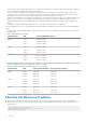
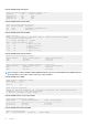
• Globally configure an anycast MAC address for all VTEPs in all virtual networks. For example, if you use three VTEP switches in three
virtual networks:
Table 1. MAC address for all VTEPs
Virtual network VTEP Anycast gateway MAC address
VNID 11
VTEP 1
VTEP 2
VTEP 3
00.11.22.33.44.55
00.11.22.33.44.55
00.11.22.33.44.55
VNID 12
VTEP 1
VTEP 2
VTEP 3
00.11.22.33.44.55
00.11.22.33.44.55
00.11.22.33.44.55
VNID 13
VTEP 1
VTEP 2
VTEP 3
00.11.22.33.44.55
00.11.22.33.44.55
00.11.22.33.44.55
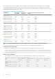
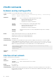
• Configure a unique IP address on the virtual-network interface on each VTEP across all virtual networks. Configure the same anycast
gateway IP address on all VTEPs in a virtual-network subnet. For example:
Table 2. IP address on the virtual-network interface on each VTEP
Virtual network VTEP Virtual-network IP address Anycast gateway IP address
VNID 11 VTEP 1
VTEP 2
VTEP 3
10.10.1.201
10.10.1.202
10.10.1.203
10.10.1.254
10.10.1.254
10.10.1.254
VNID 12 VTEP 1
VTEP 2
VTEP 3
10.20.1.201
10.20.1.202
10.20.1.203
10.20.1.254
10.20.1.254
10.20.1.254
VNID 13 VTEP 1
VTEP 2
VTEP 3
10.30.1.201
10.30.1.202
10.30.1.203
10.30.1.254
10.30.1.254
10.30.1.254
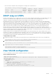
Advertise VXLAN source IP address
1. Advertise the IP address of the local source tunnel interface to all VTEPs in the underlay IP network using the existing routing
infrastructure. This example uses OSPF to advertise the VXLAN source IP address on Ethernet1/1/3, which is the underlay network-
facing interface:
OS10(config)# router ospf 100
OS10(config-ospf)# router-id 110.111.170.195
OS10(config-ospf)# exit
12
VXLAN