
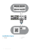
Install Guide


LED Description
• Solid green—Port link at 4x25G on a QSFP28 port or 4x10G on
a QSFP+ port
• Flashing green—Port activity at 4x25G on a QSFP28 port
• Solid yellow—Port link at 4x10G on a QSFP28 port
• Flashing yellow, 1 second on/o—Port beacon—Port activity at
4x10G on a QSFP28 port
Link/Activity LED—2x50G
• O—No link
• Solid yellow—Port link at 2x50G on a QSFP28 port
• Flashing yellow—Port activity at 2x50G on a QSFP28 port
• Flashing yellow, 1 second on/o—Port beacon
Prerequisite
NOTE: For detailed installation instructions, see Site preparations and S4112-ON Series installation sections.
The following is a list of required and optional components for the S4112–ON Series switch:
• S4112F-ON or S4112T-ON switch
• AC country- and regional-specic cables to connect the AC power source to each of the switches’ AC power supplies
• Metal wire clips for AC power cables
• Dual tray or single rails, not included
• Screws for rack installation, not included
• #1 and #2 Phillips screwdrivers, not included
• Torx screwdriver, not included
• Ground cable screws, included
• Copper or ber cables
Other optional components are:
• AC or DC ground cable for the frame-end of the ground cable
• AC ground lug
• Extra power supply unit
NOTE
: The DC ground lug kit ships with the other accessories inside the shipping box.
S4112–ON Series congurations
The S4112–ON Series (S4112F-ON and S4112T-ON) switch is available in several dierent congurations.
All S4112–ON Series switches include the following congurations:
• AC power supply with airow from the I/O side to the PSU side—normal
• AC power supply with airow from the PSU side to the I/O side—reverse
• DC power supply with airow from the I/O side to the PSU side—normal
• DC power supply with airow from the PSU side to the I/O side—reverse
The following table lists each S4112-ON Series switch conguration:
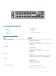
S4112–ON Series switch
13