
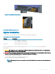
Install Guide

2 Open the container or remove the container top.
3 Carefully remove the switch from the container and place it on a secure and clean surface.
4 Remove all packing material.
5 Inspect the product and accessories for damage.
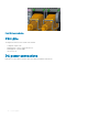
Ground cable
NOTE: For an AC-powered switch, although the third conductor of the AC power cord provides a ground path, Dell EMC
recommends grounding your switch with a dedicated ground wire.
NOTE: For a DC-powered switch, the only way to safely ground your switch is to attach a dedicated ground wire. The ground lug
kit ships in a plastic bag placed with the other accessories inside the shipping box. The ground lug bracket screws ship attached
to the switch. Before you install the DC switch in the dual-tray, attach the ground lug and bracket to the switch using the
included screws and then attach the DC ground wire to the ground lug.
The ground cable is not included. To properly ground the chassis, Dell EMC recommends a one- or two-hole lug, M4 hole size. The ground
lugs must be a UL-recognized, crimp-type lug.
CAUTION: Grounding conductors
must
be made of copper. Do not use aluminum conductors.
NOTE: Coat the one-hole lug with an anti-oxidant compound before crimping. Also, bring any unplated mating surfaces to a shiny
nish and coat with an anti-oxidant before mating. Plated mating surfaces must be clean and free from contamination.
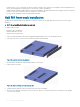
Before you install the switch into the dual-tray:
1 Cut the ground cable (not included) to the desired length. The cable length must facilitate proper operation of the fault interrupt
circuits. Use the shortest cable route allowable.
2 Unscrew the two attached M4 screws and set aside.
3 Attach the ground lug and bracket to the switch using the M4 screws.
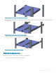
4 Using one of the two M4 threaded holes, attach the ground cable to the lug. Use the M4 screw with a captive internal tooth lock
washer. Torque the screw to ±5-6 in-lbs.
5 Attach the other end of the ground cable to a suitable ground point such as the rack or cabinet.
The rack installation ears are not a suitable grounding point.
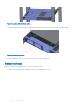
Rack or cabinet installation
You may either place the switch on a rack shelf or mount the switch directly into a 19" wide, EIA-310- E-compliant rack. The dual-tray
mounting rails ship with the dual tray, not the switch.
WARNING
: This guide is a condensed reference. Read the safety instructions in your
Safety, Environmental, and Regulatory
information booklet before you begin.
NOTE: The illustrations in this section are not intended to represent a specic switch.
NOTE: Do not the use the mounted rails as a shelf or a workplace.
Rack mount safety considerations
• Rack loading—Overloading or uneven loading of racks may result in shelf or rack failure, possibly damaging the equipment and causing
personal injury. Stabilize racks in a permanent location before loading begins. Mount the components starting at the bottom of the rack,
then work to the top. Do not exceed your rack’s load rating.
• Power considerations—Connect only to the power source specied on the unit. When you install multiple electrical components in a
rack, ensure that the total component power ratings do not exceed the circuit capabilities. Overloaded power sources and extension
cords present re and shock hazards.
• Elevated ambient temperature—If you install the switch in a closed rack assembly, the operating temperature of the rack environment
may be greater than the room ambient temperature. Use care not to exceed the 45°C (113°F) maximum ambient temperature of the
switch.
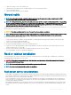
S4112–ON Series installation
21