
Reference Guide


1 Congure a VLT domain and enter VLT-DOMAIN mode. Congure the same VLT domain ID on each peer, from 1 to 255.
vlt-domain domain-id
2 Repeat the steps on the VLT peer to create the VLT domain.
Peer 1
OS10(config)# vlt-domain 1
OS10(conf-vlt-1)#
Peer 2
OS10(config)# vlt-domain 1
OS10(conf-vlt-1)#
VLTi conguration
Before you congure VLTi on peer interfaces, remove each interface from L2 mode with the no switchport command, see VLT
interconnect.
1 Enter the VLT domain ID to enter from CONFIGURATION mode.
vlt-domain domain-id
2 Congure one or a hyphen-separated range of VLT peer interfaces to become a member of the VLTi in INTERFACE mode.
discovery-interface {ethernet node/slot/port[:subport] | ethernet node/slot/port[:subport] -
node/slot/port[:subport]}
3 Repeat the steps on the VLT peer.
Peer 1
OS10(config)# interface ethernet 1/1/1
OS10(conf-if-eth1/1/1)# no switchport
OS10(conf-if-eth1/1/1)# exit
OS10(config)# interface ethernet 1/1/2
OS10(conf-if-eth1/1/2)# no switchport
OS10(conf-if-eth1/1/2)# exit
OS10(config)# vlt-domain 1
OS10(conf-vlt-1)# discovery-interface ethernet1/1/1
OS10(conf-vlt-1)# discovery-interface ethernet1/1/2
Peer 2
OS10(config)# interface ethernet 1/1/1
OS10(conf-if-eth1/1/1)# no switchport
OS10(conf-if-eth1/1/1)# exit
OS10(config)# interface ethernet 1/1/2
OS10(conf-if-eth1/1/2)# no switchport
OS10(conf-if-eth1/1/2)# exit
OS10(config)# vlt-domain 1
OS10(conf-vlt-1)# discovery-interface ethernet1/1/1
OS10(conf-vlt-1)# discovery-interface ethernet1/1/2
Congure VLT port-channel
A VLT port-channel links an attached device and VLT peer switches, also known as a virtual link trunk.
1 Enter the port-channel ID number on the VLT peer in INTERFACE mode, from 1 to 1024.
interface port-channel id-number
2 Assign the same ID to a VLT port-channel on each VLT peer — peers are seen as a single VLT LAG to downstream devices.
vlt-port-channel vlt-lag-id
3 Repeat the steps on the VLT peer.
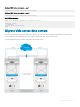
Virtual link trunking
605