
API Guide

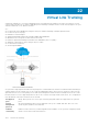

Virtual Link Trunking
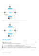
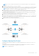
Virtual Link Trunking (VLT) is a Layer 2 aggregation protocol used between an end device such as a server and two or more
connected network devices. VLT helps to aggregate ports terminating on multiple switches. OS10 currently supports VLT port
channel terminations on two different switches.
VLT:
● Provides node-level redundancy by using the same port channel terminating on multiple upstream nodes.
● Provides a loop-free topology
● Eliminates STP-blocked ports
● Optimizes bandwidth utilization by using all available uplink bandwidth
● Guarantees fast convergence if either a link or device fails
● Enhances optimized forwarding with Virtual Router Redundancy Protocol (VRRP)
● Optimizes routing with VLT peer routing for Layer-3 VLANs
● Provides link-level resiliency
● Assures high availability
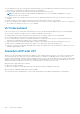
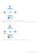
VLT presents a single logical L2 domain from the perspective of attached devices that have a virtual link trunk terminating on
separate nodes in the VLT domain. The two VLT nodes are independent Layer2/ Layer3 (L2/L3) switches for devices in the
upstream network. L2/L3 control plane protocols and system management features function normally in both the VLT nodes.
External switches or servers supporting LACP see the two VLT switches as a single virtual switch. Hence, VLT configurations
must be identical on both the switches in the VLT domain.
VLT physical
ports
802.1p, 802.1q, LLDP, flow control, port monitoring, and jumbo frames are supported on VLT physical
ports.
System
management
protocols
All system management protocols are supported on VLT ports—SNMP, AAA, ACL, DNS, FTP, SSH,
system log, NTP, RADIUS, SCP, and LLDP.
L3 VLAN
connectivity
Enable L3 VLAN connectivity, VLANs assigned with an IP address, on VLT peers by configuring a VLAN
interface for the same VLAN on both devices.
22
1274 Virtual Link Trunking