Dell EMC SmartFabric Services User Guide Release 1.0 March 2021 Rev.
Notes, cautions, and warnings NOTE: A NOTE indicates important information that helps you make better use of your product. CAUTION: A CAUTION indicates either potential damage to hardware or loss of data and tells you how to avoid the problem. WARNING: A WARNING indicates a potential for property damage, personal injury, or death. © 2020 -2021 Dell Inc. or its subsidiaries. All rights reserved. Dell, EMC, and other trademarks are trademarks of Dell Inc. or its subsidiaries.
Contents Chapter 1: About this guide........................................................................................................... 5 Text and Syntax Conventions.......................................................................................................................................... 5 Related Documents.............................................................................................................................................................
SFS personalities............................................................................................................................................................... 38 Support matrix................................................................................................................................................................... 39 Fabric operations and life cycle management............................................................................................................
1 About this guide This guide provides information regarding the integration of SmartFabric Services (SFS) with Dell EMC VxRail, Dell EMC PowerEdge MX, and Dell EMC Isilon/Dell EMC PowerScale devices.
Dell EMC Demo Center The Dell EMC Demo Center is a highly scalable, cloud-based service that provides 24/7 self-service access to virtual labs, hardware labs, and interactive product simulations. Several interactive demos are available on the Demo Center. Contact Dell Support to get access to the Demo Center. Documentation Feedback Dell Technologies strives to provide accurate and comprehensive documentation and welcomes your suggestions and comments.
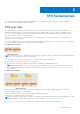
2 SFS fundamentals This chapter provides information about the fundamentals of SFS including overview, supported topologies and platforms, network fabric formation, and its supported solutions. SFS overview SFS is a SmartFabric OS10 feature that provides network fabric automation and API-based programming capabilities. SFS has different personalities that can be integrated with systems including VxRail, PowerScale, generic PowerEdge servers, PowerStore, storage, and MX servers.
This guide covers the following SFS qualified solutions: ● SFS deployment with VxRail ● SFS deployment with PowerEdge MX ● SFS deployment with Isilon/PowerScale SFS GUI OS10 has support for SFS GUI to set up the initial SFS configurations in a L3 leaf and spine topology. You access the SFS GUI using the latest version of the following browsers: ● Google Chrome ● Mozilla Firefox ● Microsoft Edge For more information about SFS GUI, see Access fabric setup configuration.
Dynamic server onboarding When the servers are connected to the fabric, SFS discovers the servers automatically. SFS discovers a host as known servers based on the specific custom originator TLVs in LLDPDUs sent through the connected ports. Following are the list of known servers discovered by SFS : ● VxRail NOTE: SFS discovers and onboards the VxRail server automatically. ● PowerStore X ● PowerStore T When a known server is discovered on the server-facing port, SFS applies the server profile configuration.
● The bonding can be static or LACP. ● All existing bonding modes are supported on a statically onboarded server. ● VXLAN does not support STP on access ports and it is not applicable for L3 Fabric. For the VXLAN type of network, you cannot configure STP; the network topology must remain loop free. ● All existing network types are allowed to be onboarded on statically onboarded servers.
3 Setting up SFS This chapter explains the workflow to setup SFS including initializing SFS and enabling it on leaf and spine switches. Prerequisites Ensure that the following are met before enabling SFS on the switches: ● Configure the Out-of-band (OOB) management configuration on the leaf switches. OOB management network enables connections to the SFS GUI. Dell EMC PowerSwitch S3048-ON can function as an OOB management switch with the OS10 factory default configuration.
SFS behavior SFS elects one switch from the fabric as a master switch and designates the remaining leaf switches as the backup switches. In the event of a master failover, a new master is elected from the backup switches using the keepalive information. The switches that are configured as Preferred Master have a higher priority to become the master switch. If none of the switches are configured as the preferred master, any leaf switch can become the master.
Leaf: In SFS, the two leaf switches are automatically configured as a VLT pair. OS10(config)# smartfabric l3fabric enable role LEAF vlti ethernet 1/1/4-1/1/5 Reboot to change the personality? [yes/no]: yes In the above example, the Ethernet interfaces 1/1/4 and 1/1/5 are the VLTi interfaces. In Isilon or PowerScale back-end deployments, when enabling SFS in a leaf and spine topology, no VLTi configuration is required for the leaf switch.
Example—Usage of curl command on a linux server is as shown: Enable SmartFabric Services L2 personality using script In SFS L2 personality, you can enable SFS only using API. All deployments from SmartFabric OS10.4.1.4 to OS10.5.0.x version support only the single rack network fabric. NOTE: The L2 personality is not available for new deployments after 10.5.0.5 release. A python script is used to enable SFS.
Spine: Leaf: After you enable SFS on a switch, the system reloads to apply the configuration. 6. Repeat the steps 1 to 4 on all the remaining switches to enable SFS and set role. All switches reload and forms a fabric. Verify the switch operating mode To verify that the switches are in SmartFabric mode, run the show switch-operating-mode command on each switch.
Disable SFS using CLI To delete the existing switch configuration and go back to Full Switch mode, run the no smartfabric l3fabric command on each switch. The no smartfabric l3fabric command disables the L3 fabric personality. After you disable the L3 fabric in the switch, the system prompts for confirmation and reboots in Full Switch mode.
4 Deploying and managing a fabric You can use SFS GUI to set up initial SFS configuration in a leaf and spine topology. The SFS GUI helps you with the initial SFS deployment operations and management of the switches in a fabric. Access fabric setup options Follow the instructions to access fabric setup options: 1. Log in to SmartFabric Services GUI using the management IP address of any switch. 2.
Mouse over a fabric to see the detailed information about the leaf and spine switches, and the link connectivity. The session is controlled through token-based authentication. The default token timeout value is 120 minutes. You are automatically logged out, after the token time expires with a warning message. Update default fabric, switch names, and descriptions SFS assigns unique names for the network fabric, racks, and switches automatically.
3. Change the name and description of the rack or VLT fabric, and click Next. 4. Change the name and description of the switches, and click Finish. NOTE: If you change the switch name in the GUI, the hostname on the switch CLI is also updated. Create uplink for external network connectivity Uplinks enable the network fabric to communicate with the external network. Before creating an uplink, ensure that the external network is configured with the L2 or L3 setup.
2. Select the Uplink Connectivity as Layer 2, enter the name and description, and click Next. NOTE: You can create L2 uplinks only on leaf switches. 3. Select a rack and one or more interfaces from the leaf switches to associate to the uplinks. If you want to split a port speed, breakout the interface first before associating the interface to the uplinks. See Breakout Switch Ports to configure breakout the ports from SFS GUI. 4.
6. Select Yes or No appropriately to integrate the networks that are created automatically in the fabric through vCenter on this uplink. When you select Yes, the uplink is created with the type Default and the networks from the vCenter are automatically appended to the L2 uplink during vCenter integration. For more information, see OpenManage Network Integration for SmartFabric Services User Guide, Release 2.0. 7. Click Finish.
3. Create a L3 VLAN uplink by providing the name and description, and click Next. NOTE: You can create L3 uplinks on both leaf and spine switches. 4. Associate the interfaces of the spine or leaf switches with the L3 uplink. ● Spine—Select a spine switch and an interface or multiple interfaces of the spine switch to be associated with the uplink.
● Leaf—Select a leaf switch from the rack, and an interface or multiple interfaces of the leaf switch to be associated with the uplink. 5. 6. 7. 8. 9. Select the static or dynamic LAG based on the configuration setup in the external network, and click Next. Create a L3 VLAN network by providing name, description, and VLAN ID, and associate to the selected interfaces. Select if the network is a tagged or an untagged network. Enter the IP address for the network.
● eBGP—A routing policy template that contains BGP peer IP address and the remote AS number. NOTE: The network configurations reflect in the switch only after associating the network with an uplink or server profile. 10. Click Finish. Click Routing Profiles tab to view the list of all the routing profiles that are configured in the SFS. For more information, see Manage routing profiles. Configure L3 Routed uplink Use the following procedure to create a L3 routed uplink: 1.
7. Define a routing policy to associate with the uplink based on the external network connectivity setup. ● Static Route—A route policy template that contains a network prefix and the next hop IP address. ● eBGP—A routing policy template that contains BGP peer IP address and the remote AS number. NOTE: You cannot associate a L3 Routed network with more than one uplink or server profile.
To delete an uplink: 1. Select an uplink from the list and click Delete. 2. Click Ok to confirm deletion. NOTE: When you delete an uplink, the network and route profile that are associated with the uplink are not deleted. Breakout switch ports You can configure breakouts for the Ethernet ports or port-group only on the leaf switches to connect to the external device or jump host. Use the following procedure to breakout switch ports: 1. Click Home > Breakout Switch Ports. 2. Select the rack from the list.
Configure jump host A jump host is a designated port to which an external device such as a laptop can be connected. You can configure only one port in a leaf switch port as a jump host for the external device to connect to L3 fabric. Select any available port that is not part of an uplink, ICL, and port connected to a server in fabric. In VxRail deployment, a jump host is primarily used to bring up a VxRail cluster.
3. Enter interface IP address, gateway, and DHCP helper IP address to change a L2 network to a L3. 4. Click Ok to complete the configuration. Create a network You can create the following type of networks: ● General purpose networks ● VXLAN networks ● L3 VLAN networks ● L3 Routed networks For detailed information about these network types, see Networks. You can create these networks using the Update Network Configuration option available in the SFS GUI.
3. Enter the required details to create any network of general purpose, VXLAN, L3 VLAN, or L3 Routed type. Click Network Profiles tab to view the list of networks that are created in the fabric. For more information, see Network profiles. Onboard a server onto the fabric See Server discovery and onboarding for more information about server onboarding and its types. You can onboard a server statically or dynamically.
3. Select an interface ID from the list and click Next. SFS discovers some of the servers dynamically and if you are onboarding a discovered interface, the server interface ID lists all the discovered interface. 4. Select No for Static Onboarding and click Next. NOTE: Dell Technologies recommends that you use dynamic onboarding for the discovered interfaces. 5. Associate the networks to the server interface profile from the list or create a network or virtual network according to the network connectivity.
Onboard nondiscovered server interfaces Use the following procedure to onboard the server statically for nondiscovered server interfaces: 1. Click Onboard a Server onto the Fabric. 2. Select the server profile from the list or create a profile for the interface using Add Server Profile. 3. This option is used for onboarding servers that are not discovered by SFS. Select No for discovered server interface and enter the Server Interface ID and click Next.
5. Assign an interface of the leaf switch and click Next. 6. Associate the networks with the server interface profile from the list or create a network or virtual network according to the network connectivity. For more information, see Networks. This step has options to create network and virtual networks.
Edit default fabric settings Use the following procedure to edit the default fabric settings: 1. Click Home > Edit Default Fabric Settings. 2. Change the values of the default settings as required. 3. Click OK. The changed settings are applied only after a reboot. The system prompts for confirmation to continue. After you click OK, all the switches in the network fabric reload to apply the fabric setting changes.
2. Click Choose File and select the backup configuration file that is stored externally, and click Ok. 3. Select the check box to agree and click OK to confirm. All switches in the fabric reboot to apply the new configurations. Manage network profiles You can view and manage the network profiles that are created in a fabric. Click the Network Profiles tab to view a list of all networks and virtual networks that are configured in the SFS. You can also delete a network profile from this tab.
Virtual Networks—Displays only the virtual networks available in the fabric. Delete a network profile You can delete a network profile: 1. Click the Networks or Virtual Networks tab and select a profile from the list. 2. Click Delete. 3. Click Ok to confirm. Manage routing profiles You can view and manage the routing profiles that are configured in SFS. You can delete a routing profile from this tab. The routing profiles are created as part of uplink configuration workflow.
Route Profile—Displays detailed routing profile information. Profile Switch Mapping—Displays the list of profiles that are mapped to the switch. Delete a routing profile You can delete a routing profile or profile switch mapping: 1. Click Routing Profiles > Route Profile or Profile Switch Mapping. 2. Select a routing profile from the list and click Delete. 3. Click Ok to confirm deletion.
5 SFS with VxRail SFS, used in leaf and spine network, creates a fully integrated solution between the fabric and a hyperconverged domain infrastructure such as VxRail. When integrated with VxRail, SFS automates network setup, simplifying and accelerating the deployment. Switches are automatically configured. When additional VxRail nodes are connected, the fabric identifies them as VxRail nodes and automatically onboards the nodes to the required networks.
● ● ● ● SmartFabric OS10 OMNI VxRail Manager VMware vCenter For more information regarding detailed deployment requirements, see the Deployment Guides for respective releases. Supported switches Following is the Dell EMC PowerSwitch typical roles in SFS with VxRail deployment. Table 4.
Table 5. SFS personalities in VxRail deployment L2 Single Rack personality L3 multi rack personality Enabled SFS by running a Python script in the OS10 Linux shell. Enable SFS using CLI, API, or UI. Existing deployments when upgraded to SmartFabric OS10.5.0.5 continue to run in the L2 fabric profile and L3 fabric capabilities are not available. If you upgrade switches with L2 personality to OS10.5.0.5, SFS operates with the VxRail L2 single rack personality.
6 SFS with PowerEdge MX Dell EMC PowerEdge MX is a unified, high-performance data center infrastructure providing the agility, resiliency, and efficiency to optimize a wide variety of traditional and new emerging data center workloads and applications. In a Dell EMC PowerEdge MX7000 infrastructure, the MX9116n fabric engine and MX5108n Ethernet switch support SFS.
7 SFS for Isilon/PowerScale back-end fabric Dell EMC PowerScale is a scale-out network-attached storage (NAS) platform that supports unstructured data workloads. All PowerScale models are powered by the OneFS operating system. PowerScale uses Dell EMC PowerSwitches to provide the network. SmartFabric OS10 with SFS, for PowerScale back-end fabric automates onboarding and network configuration of PowerScale devices on a L3 leaf and spine fabric. Isilon OneFS interacts with back-end fabric formed by SFS.
PowerScale requirements Requirements specific to SFS with PowerScale deployment are as follows : ● By default, all PowerSwitches for PowerScale deployment are shipped with factory-loaded OS10. NOTE: Dell EMC PowerSwitches must be running SmartFabric OS10.5.0.5 or later software releases that support the PowerScale with SFS deployment. ● In SFS with PowerScale deployment, the leaf nodes are not connected as a VLT pair. On the leaf switch, no ICL configuration is required while enabling SFS.
8 SFS commands You can run show commands specific to SFS from the CLI to view fabric configuration information. The command output varies depending on the SFS deployment. smartfabric l3fabric enable Enables SFS on the switches and creates a L3 network fabric.
Command Mode CONFIGURATION Usage Information Use this command to configure or update the VLTi information after SFS is enabled on the switch. The system reloads with the configured VLTi ports. This command can be used only if the switch should already be in L3 fabric mode. If not, enable the L3 fabric personality first and run this command. If you use any of the existing ports for the VLTi, those ports should also be specified as part of the VLTi configuration using the SmartFabric Services commands.
Default None Command Mode EXEC Usage Information This command is supported in both Full Switch and SmartFabric modes. Example (IOM) MX9116N-A1# show smartfabric cluster ---------------------------------------------------------CLUSTER DOMAIN ID : 119 VIP : fde1:53ba:e9a0:de14:0:5eff:fe00:1119 ROLE : BACKUP SERVICE-TAG : 3GB1XC2 MASTER-IPV4 : 10.11.105.
------------------------------------------------------------9GB1XC3 fde1:53ba:e9a0:de14:e6f0:4ff:fe3e:45dd ONLINE MASTER MX9116n SKY002L B1 Example (VxRail) Supported Releases OS10# show smartfabric cluster member Service-tag IP Address Status Role Type Chassis-Service-Tag Chassis-Slot ----------------------------------------------------------3Z4ZZP2 fde2:53ba:e9a0:cccc:54bf:64ff:fee6:e462 ONLINE BACKUP 3Z4ZZP1 fde2:53ba:e9a0:cccc:54bf:64ff:fee6:e463 ONLINE BACKUP BR2ZZP2 fde2:53ba:e9a0:cccc:3c2c:30ff:fe4
show smartfabric configured-server configuredserver-interface Displays interface-level information of the configured servers. Information includes server ID, port ID, onboarded interface, server status, fabric ID, native VLAN, network profiles, and bandwidth partition details. Syntax show smartfabric configured-server configured-server-interface server-id Parameters server-id—Enter a configured server ID information.
show smartfabric details Displays all details specific to the fabric. Details include name, description, ID, nodes that are part of the fabric, design type associated with the fabric, and status detail of a fabric. Syntax show smartfabric details Parameters None Default None Command Mode EXEC Usage Information This command is supported in both Full Switch and SFS modes.
Usage Information Example Supported Releases This command is supported in both Full Switch and SmartFabric modes.
Usage Information Example (IOM) Example (VxRail) Supported Releases This command is supported in both Full Switch and SmartFabric modes.
cd3ca1685550 (Name-Rack) Example (VxRail) Supported Releases 7222c224-223c-5fa4-a244- OS10# show smartfabric nodes node-id GGVQG02 ---------------------------------------------------------Node Name : Name-Leaf-2 Node Id : GGVQG02 Node Type : S5232F-ON Node Status : ONLINE Node Mode : FABRIC Node Ready : true Node Model : S5232F-ON Replacement Node Id : Chassis service tag : Chassis slot : Fabric : 7222c224-223c-5fa4-a244-cd3ca1685550 (Name-Rack) Fabric node status : OPERATIONAL Software Version : 10.5.
Role ICL : :ethernet1/1/29, ethernet1/1/30 OS10# show smartfabric personality Personality Role ICL Leaf1# :L3 Fabric :LEAF :ethernet1/1/5, ethernet1/1/6 OS10# show smartfabric personality Personality Role ICL Supported Releases :L3 Fabric :SPINE : ● MX9116n and MX5108n—10.5.0.1 or later ● SFS-supported OS10 switches—10.5.0.3 or later show smartfabric uplinks Displays all uplink-related information in the SFS.
Untagged-network : Networks : Network780 Configured-Interfaces : CAC00N2:ethernet1/1/22:2 ------------------------------------------------------------------------------------------------------------------Name : L3VLANUplink Description : Uplink On L3VLAN Network800 ID : L3VLANUplink-800 Media Type : ETHERNET Native Vlan : 0 Untagged-network : Networks : Network800 Configured-Interfaces : CAC00N2:ethernet1/1/22:1 ------------------------------------------------------------------------------------------------
Upgrade Protocol Upgrade start time Status Nodes to Upgrade Reboot Sequence : : : : PUSH 2021-02-12 01:51:29.
Recommended Action:Make sure that the VLTi cables are connected to the correct ports as per the selected fabric design.
9 Appendix This chapter covers additional information that can support you with the fabric configuration tasks. Internal fabric components and networks SFS automatically creates the following components and networks: Internal SFS components SFS creates a VLT fabric automatically in the leaf and spine environment. VLT fabric is autoassigned with a fabric-ID, a universally unique identifier (UUID).
NOTE: You can change this VLAN to a specified VLAN through SFS GUI. VLAN 3939— Default client control network SFS configures a second overlay network that is called Client_Control_Network for SFS-integrated solutions. When a device such as VxRail is discovered, it is automatically added as a tagged member of this network. SFS enables master advertisement and fabric discovery by integrated solutions. The SFS master virtual IP address for VXLAN network is advertised.
● MST with instance id 62: All the SFS reserved VLANs (4001-4091) are part of this configuration. On this MSTI, spanning tree is disabled. ● All user created VLANs are part of CST (default MST instance), which interoperates with RSTP. STP is enabled for this MSTI. You can change the mode to MSTP once the fabric is created. When you change the mode, the whole fabric goes through a reboot cycle and the new mode is set to MSTP. NOTE: Changing the STP mode impact the traffic flow in the cluster.
● Pair of IP addresses to be assigned to the VLT pair ● VRRP gateway IP address for VIP L3 VLAN network contains a list of IP addresses and a gateway IP address. Optionally, you can specify DHCP relay addresses. You can configure and attach a L3 VLAN network to an uplink. Each VLTi uplink interface contains an IP address that is allocated from the list of IP addresses that are configured on the L3 VLAN network. L3 Routed network L3 routed network is used to assign IP address on a single interface.
eBGP peer routing profile—An eBGP peer routing profile is a routing template that contains BGP remote addresses and the remote AS number. A remote address can be an interface address or a loopback address. During uplink creation, you can associate this policy to uplink created on one or more switches in a fabric. When this policy is created, a BGP session is configured on the switch.