
Connectivity Guide
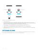

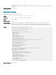

Table Of Contents
- OS10 Enterprise Edition User Guide Release 10.4.2.0
- Getting Started
- Supported Hardware
- Download OS10 image and license
- Installation using ONIE
- Log into OS10
- Install OS10 license
- Zero-touch deployment
- Remote access
- Upgrade OS10
- CLI Basics
- User accounts
- Key CLI features
- CLI command modes
- CLI command hierarchy
- CLI command categories
- CONFIGURATION Mode
- Command help
- Check device status
- Candidate configuration
- Change to transaction-based configuration mode
- Copy running configuration
- Restore startup configuration
- Reload system image
- Filter show commands
- Alias command
- Batch mode
- Linux shell commands
- SSH commands
- OS9 environment commands
- Common commands
- alias
- alias (multi-line)
- batch
- boot
- commit
- configure
- copy
- default (alias)
- delete
- description (alias)
- dir
- discard
- do
- feature config-os9-style
- exit
- license
- line (alias)
- lock
- management route
- move
- no
- reload
- show alias
- show boot
- show candidate-configuration
- show environment
- show inventory
- show ip management-route
- show ipv6 management-route
- show license status
- show running-configuration
- show startup-configuration
- show system
- show version
- start
- system
- system identifier
- terminal
- traceroute
- unlock
- write
- Interfaces
- Ethernet interfaces
- Unified port groups
- L2 mode configuration
- L3 mode configuration
- Fibre Channel interfaces
- Management interface
- VLAN interfaces
- User-configured default VLAN
- VLAN scale profile
- Loopback interfaces
- Port-channel interfaces
- Configure interface ranges
- Switch-port profiles
- Configure breakout mode
- Breakout auto-configuration
- Forward error correction
- Energy-efficient Ethernet
- View interface configuration
- Interface commands
- channel-group
- default vlan-id
- description (Interface)
- duplex
- feature auto-breakout
- fec
- interface breakout
- interface ethernet
- interface loopback
- interface mgmt
- interface null
- interface port-channel
- interface range
- interface vlan
- link-bundle-utilization
- mode
- mode l3
- mtu
- port-group
- scale-profile vlan
- show interface
- show inventory media
- show link-bundle-utilization
- show port-channel summary
- show port-group
- show switch-port-profile
- show vlan
- shutdown
- speed (Fibre Channel)
- speed (Management)
- switch-port-profile
- switchport access vlan
- switchport mode
- switchport trunk allowed vlan
- Fibre Channel
- Layer 2
- 802.1X
- Link Aggregation Control Protocol
- Link Layer Discovery Protocol
- Protocol data units
- Optional TLVs
- Organizationally-specific TLVs
- Media endpoint discovery
- Network connectivity device
- LLDP-MED capabilities TLV
- Network policies TLVs
- Define network policies
- Packet timer values
- Disable and re-enable LLDP
- Disable and re-enable LLDP on management ports
- Advertise TLVs
- Network policy advertisement
- Fast start repeat count
- View LLDP configuration
- Adjacent agent advertisements
- Time to live
- LLDP commands
- Media Access Control
- Multiple Spanning-Tree
- Rapid per-VLAN spanning-tree plus
- Rapid Spanning-Tree Protocol
- Virtual LANs
- Port monitoring
- Layer 3
- Virtual routing and forwarding
- Bidirectional Forwarding Detection
- Border Gateway Protocol
- Sessions and peers
- Route reflectors
- Multiprotocol BGP
- Attributes
- Selection criteria
- Weight and local preference
- Multiexit discriminators
- Origin
- AS path and next-hop
- Best path selection
- More path support
- Advertise cost
- 4-Byte AS numbers
- AS number migration
- Configure Border Gateway Protocol
- Enable BGP
- Configure Dual Stack
- Configure administrative distance
- Peer templates
- Neighbor fall-over
- Configure password
- Fast external fallover
- Passive peering
- Local AS
- AS number limit
- Redistribute routes
- Additional paths
- MED attributes
- Local preference attribute
- Weight attribute
- Enable multipath
- Route-map filters
- Route reflector clusters
- Aggregate routes
- Confederations
- Route dampening
- Timers
- Neighbor soft-reconfiguration
- BGP commands
- Equal cost multi-path
- IPv4 routing
- IPv6 routing
- Internet Group Management Protocol
- Multicast Listener Discovery Protocol
- Open shortest path first
- Object tracking manager
- Policy-based routing
- Virtual Router Redundancy Protocol
- VXLAN
- VXLAN concepts
- VXLAN as NVO solution
- Configure VXLAN
- VXLAN commands
- member-interface
- nve
- remote-vtep
- show nve remote-vtep
- show nve remote-vtep counters
- show nve vxlan-vni
- show virtual-network
- show virtual-network counters
- show virtual-network interface counters
- show virtual-network interface
- show virtual-network vlan
- show vlan (virtual network)
- source-interface loopback
- virtual-network
- virtual-network untagged-vlan
- vxlan-vni
- VXLAN MAC commands
- clear mac address-table dynamic nve remote-vtep
- clear mac address-table dynamic virtual-network
- show mac address-table count extended
- show mac address-table count nve
- show mac address-table count virtual-network
- show mac address-table extended
- show mac address-table nve
- show mac address-table virtual-network
- Example: VXLAN with static VTEP
- BGP EVPN for VXLAN
- UFT modes
- System management
- Dynamic Host Configuration Protocol
- Network Time Protocol
- System clock
- System banners
- User session management
- Telnet server
- Security
- User re-authentication
- Password strength
- Role-based access control
- Assign user role
- RADIUS authentication
- TACACS+ authentication
- TACACS+ unknown or missing user role
- SSH server
- Virtual terminal line
- Enable AAA accounting
- Enable user lockout
- Limit concurrent login sessions
- Enable login statistics
- Security commands
- Simple Network Management Protocol
- OS10 image upgrade
- OpenFlow
- Access Control Lists
- IP ACLs
- MAC ACLs
- Control-plane ACLs
- IP fragment handling
- L3 ACL rules
- Assign sequence number to filter
- Delete ACL rule
- L2 and L3 ACLs
- Assign and apply ACL filters
- Ingress ACL filters
- Egress ACL filters
- Clear access-list counters
- IP prefix-lists
- Route-maps
- Match routes
- Set conditions
- Continue clause
- ACL flow-based monitoring
- Enable flow-based monitoring
- ACL table profiles
- View ACL table utilization report
- ACL commands
- acl-table-profile
- clear ip access-list counters
- clear ipv6 access-list counters
- clear mac access-list counters
- deny
- deny (IPv6)
- deny (MAC)
- deny icmp
- deny icmp (IPv6)
- deny ip
- deny ipv6
- deny tcp
- deny tcp (IPv6)
- deny udp
- deny udp (IPv6)
- description
- hardware acl-table-profile
- ingress app-group
- ip access-group
- ip access-list
- ip as-path access-list
- ip community-list standard deny
- ip community–list standard permit
- ip extcommunity-list standard deny
- ip extcommunity-list standard permit
- ip prefix-list description
- ip prefix-list deny
- ip prefix-list permit
- ip prefix-list seq deny
- ip prefix-list seq permit
- ipv6 access-group
- ipv6 access-list
- ipv6 prefix-list deny
- ipv6 prefix-list description
- ipv6 prefix-list permit
- ipv6 prefix-list seq deny
- ipv6 prefix-list seq permit
- mac access-group
- mac access-list
- permit
- permit (IPv6)
- permit (MAC)
- permit icmp
- permit icmp (IPv6)
- permit ip
- permit ipv6
- permit tcp
- permit tcp (IPv6)
- permit udp
- permit udp (IPv6)
- remark
- seq deny
- seq deny (IPv6)
- seq deny (MAC)
- seq deny icmp
- seq deny icmp (IPv6)
- seq deny ip
- seq deny ipv6
- seq deny tcp
- seq deny tcp (IPv6)
- seq deny udp
- seq deny udp (IPv6)
- seq permit
- seq permit (IPv6)
- seq permit (MAC)
- seq permit icmp
- seq permit icmp (IPv6)
- seq permit ip
- seq permit ipv6
- seq permit tcp
- seq permit tcp (IPv6)
- seq permit udp
- seq permit udp (IPv6)
- show access-group
- show access-lists
- show acl-table-profile
- show acl-table-usage detail
- show ip as-path-access-list
- show ip community-list
- show ip extcommunity-list
- show ip prefix-list
- Route-map commands
- continue
- match as-path
- match community
- match extcommunity
- match interface
- match ip address
- match ip next-hop
- match ipv6 address
- match ipv6 next-hop
- match metric
- match origin
- match route-type
- match tag
- route-map
- set comm-list add
- set comm-list delete
- set community
- set extcomm-list add
- set extcomm-list delete
- set extcommunity
- set local-preference
- set metric
- set metric-type
- set next-hop
- set origin
- set tag
- set weight
- show route-map
- Quality of service
- Configure quality of service
- Ingress traffic classification
- Egress traffic classification
- Policing traffic
- Mark Traffic
- Color traffic
- Modify packet fields
- Shaping traffic
- Bandwidth allocation
- Strict priority queuing
- Buffer management
- Congestion avoidance
- Storm control
- RoCE for faster access and lossless connectivity
- QoS commands
- bandwidth
- class
- class-map
- clear interface
- clear qos statistics
- clear qos statistics type
- control-plane
- control-plane-buffer-size
- flowcontrol
- match
- match cos
- match dscp
- match precedence
- match queue
- match vlan
- mtu
- pause
- pfc-cos
- pfc-max-buffer-size
- pfc-shared-buffer-size
- pfc-shared-headroom-buffer-size
- police
- policy-map
- priority
- priority-flow-control mode
- qos-group dot1p
- qos-group dscp
- queue-limit
- queue bandwidth
- queue qos-group
- random-detect (interface)
- random-detect (queue)
- random-detect color
- random-detect ecn
- random-detect ecn
- random-detect pool
- random-detect weight
- service-policy
- set cos
- set dscp
- set qos-group
- shape
- show class-map
- show control-plane buffers
- show control-plane buffer-stats
- show control-plane info
- show control-plane statistics
- show interface priority-flow-control
- show qos interface
- show policy-map
- show qos control-plane
- show qos egress bufffers interface
- show egress buffer-stats interface
- show qos ingress buffers interface
- show ingress buffer-stats interface
- show queuing statistics
- show qos system
- show qos system buffers
- show qos maps
- show qos wred-profile
- system qos
- trust-map
- trust dot1p-map
- trust dscp-map
- qos-map traffic-class
- trust-map
- wred
- Virtual Link Trunking
- Uplink Failure Detection
- Converged data center services
- sFlow
- RESTCONF API
- Troubleshoot OS10
- Support resources
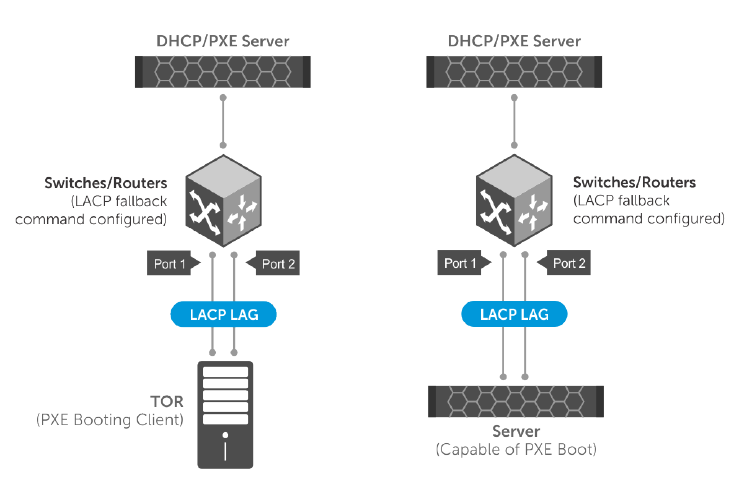
In the above scenario, LACP fallback works as follows:
1 The ToR/server boots up.
2 The switch detects the link that is up and checks fallback enabled status. If fallback is enabled, the device waits for the time-out
period for any LACP BPDUs. If there are no LACP BPDUs received within the time period, then the LAG enters into fallback mode and
adds the rst operationally UP port to the port-channel instead of placing it in an inactive state.
3 Now the ToR/server has one port up and active. The active port sends packets to the DHCP/PXE server.
4 After receiving response from the DHCP server, the ToR/server proceeds to boot from the TFTP/NFS server.
5 When the ToR/server is fully loaded with the boot image and congurations, the server starts sending LACP PDUs.
6 When the switch receives LACP PDUs from ToR/server, the device comes out of the fallback mode and activates the LAG through
normal LACP process.
LACP fallback in VLT domain
In a VLT domain, LACP fallback enables rebooting of ToR or server connected to VLT nodes through VLT port-channel. The other end of
the VLT nodes are connected to a DHCP/PXE server, as shown in the following illustration:
182
Layer 2