
White Papers

5 Dell EMC OS10 BGP eVPN Configuration Cheat Sheet | 1.0
2 Setup
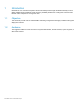
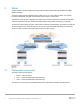
Figure1 shows the reference deployment setup used in the lab to demonstrate the Dell EMC OS10 BGP
eVPN functionality.
The setup consists of three Dell EMC switches running the 10.4.2.1.251 software release. Two dynamic
tunnels are established using BGP eVPN between the end-points (Leaf switches).
The objective of this setup is to highlight how a typical Layer 2 domain between two separate physical data
centers is stretched across an IP infrastructure while retaining and providing a flat Layer 2 connectivity.
Two VNIs are used to directly map two VLANs that are stretched (1000 and 2000). The result is two VMs that
are each assigned to vlan 1000 and 2000. The VLANs can communicate with their respective counterpart
across the Layer 3 cloud as if each VM was connected to a Layer 2 switch.
BGP eVPN VxLAN deployment diagram
2.1 Deployment components
The setup consists of three devices:
Router – Layer 3 IP-Cloud
Leaf 1 – VTEP (VXLAN/Virtual Tunnel End-Point)
Leaf 2 – VTEP (VXLAN/Virtual Tunnel End-Point)
Two dynamic VxLAN tunnels are established between the Leaf switches simulating two data centers.