S5148F-ON Installation Guide January 2019
Notes, cautions, and warnings NOTE: A NOTE indicates important information that helps you make better use of your computer. CAUTION: A CAUTION indicates either potential damage to hardware or loss of data and tells you how to avoid the problem. WARNING: A WARNING indicates a potential for property damage, personal injury, or death. © 2017 - 2019 Dell Inc. or its subsidiaries. All rights reserved. Dell, EMC, and other trademarks are trademarks of Dell Inc. or its subsidiaries.
Contents 1 About this guide............................................................................................................................................. 5 Regulatory........................................................................................................................................................................... 5 Related documents............................................................................................................................................
Optics removal........................................................................................................................................................... 29 Switch power-up..............................................................................................................................................................29 Power up sequence..................................................................................................................................................
1 About this guide This guide provides site preparation recommendations, step-by-step procedures for rack mounting and desk mounting your switch, inserting modules, and connecting to a power source. CAUTION: To avoid electrostatic discharge (ESD) damage, wear grounding wrist straps when handling this equipment. WARNING: Only trained and qualified personnel can install this equipment. Read this guide before you install and power up this equipment. This equipment contains two power cords.
Information symbols This book uses the following information symbols: NOTE: The Note icon signals important operational information. CAUTION: The Caution icon signals information about situations that could result in equipment damage or loss of data. WARNING: The Warning icon signals information about hardware handling that could result in injury. WARNING: The ESD Warning icon requires that you take electrostatic precautions when handling the device.
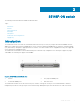
2 S5148F-ON switch The following sections describe the Dell EMC S5148F-ON switch: Topics: • Introduction • Features • Physical dimensions • LED display • Prerequisites • S5148F-ON switch configurations • Luggage tag Introduction The S5148F-ON switch is a one rack unit, full-featured, fixed form-factor top-of-rack (ToR) compact 10/25/40/50/100GbE switch.
Figure 3.
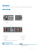
LED behavior The following S5148F-ON switch LED behavior is seen during open networking installation environment (ONIE) operations: S5148F-ON LEDs 1 Stack ID LED 2 Port Activity LED 3 Port Activity LED 4 Master LED 5 System LED 6 Locator LED 7 Fan LED 8 Power LED 9 RJ-45 Ethernet Port LED: Left is activity; right is link. Table 1.
LED Description • • Solid yellow—Critical system error Blinking yellow—Noncritical system error, fan failure, or power supply failure Power LED • • • • Off—No power Solid Green—Normal operation Solid yellow—POST is in process Blinking yellow—Power supply failed Master LED • • Off—Switch is in Stacking Slave mode Solid green—Switch is in Stacking Master or Standalone mode FAN LED • • Off—No power Solid green—Normal operation; fan powered and running at the expected RPM Solid yellow—Fan failed—incl
LED Description • Flashing green—Port activity NOTE: There are four LEDs for each SFP28 and QSFP28 port. For each port, 100GbE or 40GbE uses only one LED, 2x50GbE uses two LEDs, and 4x25GbE or 4x10GbE uses all four LEDs. Table 3. SFP28 port LEDs LED Description Link LED • • • • Off—No link Solid green—Link operating at maximum speed, 10G Solid yellow—Link operating at a lower speed,1G Flashing yellow, 1 second on/off—port beacon Activity LED • • Off—No link Flashing green—port activity Table 4.
• ReadyRail mounting brackets for rack installation, included • Screws for rack installation • #1 and #2 Phillips screw drivers, not included • Torx screwdriver, not included • Ground cable screws for L-bracket, included • Copper/fiber cables Other optional components are: • M3 or M4 ground cable screw, depending on your switch • Extra mounting brackets • Extra power supply unit • Extra fan module S5148F-ON switch configurations You can order the S5148F-ON switch in several different con
Figure 4.
3 Site preparations The S5148F-ON switch is suitable for installation as part of a common bond network (CBN). You can install the switch in: • Network telecommunication facilities • Data centers • Other locations where the National Electric Code (NEC) applies For more information about switch specifications, see Specifications. NOTE: Install the S5148F-ON switch in a rack or cabinet before installing the components.
The cabinet must meet minimum size requirements. Airflow must be in accordance with the Electronic Industries Alliance (EIA) standard. Ensure that there is a minimum of 5 inches (12.7 cm) between the intake and exhaust vents and the cabinet wall. Rack mounting When you prepare your equipment rack, ensure that the rack is grounded. Ground the equipment rack to the same ground point the power service in your area uses. The ground path must be permanent.
• Store in a dust-free environment. NOTE: ESD damage can occur when components are mishandled. Always wear an ESD-preventive wrist or heel ground strap when handling the S5148F-ON switch and accessories. After you remove the original packaging, place the S5148F-ON switch and components on an anti-static surface.
4 NEBS compliance For your switch to be network equipment building system (NEBS) compliant, follow the instructions detailed in this section. To be NEBS compliant, position your switch in the rack so that the air inlet is from the front aisle and the air exhaust is to the rear aisle.
Figure 5. GND lug assembly 1 Remove the two installed M3 screws from the lower-left side of your switch. NOTE: Keep these screws. 2 Remove the bracket assembly from the shipping bag. 3 Clean the bracket and lug surfaces thoroughly and apply an anti-oxidant solution to the mating surfaces. 4 Attach the switch ground using the Ground cable instructions. 5 Using the two removed screws, attach the GND lug bracket assembly to your switch, as shown. Torque the M3 screws to ±4-5 in-lbs. Figure 6.
Figure 7. GND lug assembly attached 6 Install your switch into your rack using the S5148F-ON switch installation instructions.
5 S5148F-ON switch installation To install the S5148F-ON switch, complete the installation procedures in the order presented in this section. Always handle the switch and components with care. Avoid dropping the switch or its field replaceable units (FRUs). NOTE: ESD damage can occur if components are mishandled. Always wear an ESD-preventive wrist or heel ground strap when handling the S5148F-ON switch and components.
4 Remove all packing material. 5 Inspect the product and accessories for damage. Rack or cabinet hardware installation You may either place the switch on a rack shelf or mount the switch directly into a 19" wide, EIA-310- E-compliant rack. Rack mounting includes four-post, two-post, or threaded mounts. The ReadyRails system is provided for 1U front-rack and two-post installations. The ReadyRails system includes separately packaged rail assemblies.
Figure 8. Separate rails Tool-less square-hole installation NOTE: For more installation instructions, see the installation labels attached to the rail assembly. CAUTION: Your switch is not NEBS Earthquake Z4-compliant if you this installation method. 1 With the ReadyRails flange ears facing outward, place one rail between the left and right vertical posts. Align and seat the back flange rail pegs in the back vertical post flange.
Figure 9. 1U tool-less nonthreaded square hole installation 2 Align and seat the front flange pegs in the holes on the front side of the vertical post. NOTE: Be sure that the rails click into place and are secure. 3 Repeat this procedure for the second rail. To remove each rail, pull on the latch release on each flange ear and unseat each rail. Two-post flush-mount installation NOTE: For more installation instructions, see the installation labels attached to the rail assembly.
Figure 10. Two-post flush-mount configuration 2 Attach one rail to the front post flange with two user-supplied screws. See item 2. 3 Slide the plunger bracket forward against the vertical post and secure the plunger bracket to the post flange with two user-supplied screws. See item 3. 4 Repeat this procedure for the second rail. Two-post center-mount installation NOTE: For more installation instructions, see the installation labels attached to the rail assembly.
Figure 11. Two-post center-mount threaded round-hole installation 2 Slide the back bracket towards the post. Secure it to the post flange with two user-supplied screws. See item 2 and 3. 3 Repeat this procedure for the second rail. Four-post threaded installation NOTE: For more installation instructions, see the installation labels attached to the rail assembly. CAUTION: To be NEBS Earthquake Z4-compliant, you must remove the tool-less latch castings described in Step 1.
Figure 12. Four-post threaded round-hole installation 2 For each rail, attach the front and back flanges to the post flanges with two user-supplied screws at each end. Switch installation You can mount the switch in the 1U front-rack or 1U two-post, flush or center configuration. The following is an example of a front-rack configuration: For the 1U two-post configurations, slide the switch into the rails in the same manner as the four-post configurations.
Figure 13. Attach switch rail 2 After installing both switch rails, line them up on the previously mounted ReadyRails and slide the switch in until it is flush with front of rack. To keep the switch from inadvertently sliding out of the rack and falling, about 3 inches before you fully insert your switch, the rail locking feature engages.
Figure 14. Front rack installation NOTE: Do not the use the mounted ReadyRails as a shelf or a workplace. 3 Tighten the two thumb screws and rack screws. To remove the switch from the rack or cabinet, press in the two side-release bars on the switch at the same time and slide the switch forward. Ground cable NOTE: For AC-powered switches, although the third conductor of the AC power cord provides a ground path, Dell EMC recommends grounding your switch with a dedicated ground wire.
To connect the ground cable to the switch, follow these steps: 1 Cut your ground cable (not included) to the desired length. The cable length must facilitate proper operation of the fault interrupt circuits. Use the shortest cable route allowable. 2 To attach the ground cable, use one of the following: • Using one threaded M3 hole, attached the ground cable to the lug using an M3 screw with a captive internal tooth lock washer. Torque the screw to ±4-5 in-lbs.
NOTE: ESD damage can occur if components are mishandled. Always wear an ESD-preventive wrist or heel ground strap when handling the S5148F-ON switch and components. Power up sequence When the switch powers up, the fans immediately come on at high speed. The fan speed slows as the switch continues to boot up. After switch placement After you have securely installed and powered on the S5148F-ON switch, for more information: • If you are using Dell EMC software, see switch documentation at www.dell.
6 Power supplies The S5148F-ON switch ships with two AC or DC power supplies. The two power supplies have two air-flow directions—from the I/O to the PSU and from the PSU to the I/O. Two PSUs are required for full redundancy, but the switch can operate with a single PSU. The PSUs are field replaceable. When running with full redundancy—two power supplies installed and running—you can remove and replace one PSU without disrupting traffic.
The PSUs have an integrated fan, which you cannot replace individually; if the fan integrated in a PSU fails, you must replace the entire PSU. You can replace the fan trays individually. For fan tray replacement procedures, see Fans. WARNING: Prevent exposure and contact with hazardous voltages. Do not attempt to operate this switch with the safety cover removed. CAUTION: Remove the power cable from the PSU before removing the PSU.
5 Repeat steps 1 through 4 if you have a redundant PSU using the second PSU slot on the S5148F-ON switch. NOTE: The S5148F-ON switch powers up when you connect the cables between the power supply and the power source. AC or DC power supply replacement CAUTION: Disconnect the power cord before removing the power supplies. Also, disconnect all power cords before servicing. NOTE: The PSU slides into the slot smoothly. Do not force a PSU into a slot as this action may damage the PSU or the S5148FON switch.
1 Strip 0.5 inches of insulation from each of the power connector’s wires, RTN and –48V. 2 Insert each of the power connector’s bare wire lengths into the wiring block. Insert RTN into one hole and –48V into the other hole. 3 Use a flat-blade screwdriver to tighten the screws that secures the bare wires into the wiring block. 4 Secure the site’s DC power source wires to the other side of the wiring block, see steps 1 and 3. WARNING: Do not cross the wires.
7 Fans The S5148F-ON switch comes from the factory with two PSUs and four fan modules installed in the switch. The fan modules and the power supplies, which have integrated fans, are hot-swappable. In addition to the power supply modules, you can order and install fan modules separately. The S5148F-ON switch supports two airflow direction options. Do not mix airflow types in a switch; you can use only a single airflow direction in a switch.
Fan LEDs • Solid green—Fan function is normal. • Flashing yellow—There is a fan fault. • Off—Fan is off. Fan module installation The fan modules in the S5148F-ON switch are field replaceable. Module slot 1 is on the left side of the switch; module slot 4 is on the right side of the switch. CAUTION: DO NOT mix airflow directions. All fans must use the same airflow direction—reverse or normal. If you mix the airflow direction, to avoid damage to the switch, you must correct the mixed airflow.
You must replace the fan air filters with new filters; you cannot clean and reuse the old fan air filters. Replacement filter media must meet the requirements found in GR-63-CORE. • Minimum dust arrestance of 65%, per ASHRAE Standard 52.1-1992. OR • Minimum Efficiency Rating Value (MERV) of 2, per ANSI/ASHRAE Standard 52.2-2007. CAUTION: For Network Equipment Building Systems (NEBS) compliance, use NEBS-approved filters. Use fan air filters with reverse blue-banded air flow switches—PSUs and fans.
8 Management ports Besides the 10/100/1000Base-T RJ-45 ports, the S5148F-ON switch provides several ports for management and storage. NOTE: The output examples in this section are for reference only. Your output may vary. Topics: • RS-232 console port access • MicroUSB-B console port access • USB storage mount • Before you install an OS • ONIE service discovery RS-232 console port access The RS-232 console port is on the PSU-side of the S5148F-ON switch. Figure 20.
• 8 data bits • 1 stop bit • No flow control MicroUSB-B console port access The MicroUSB-B console port is on the PSU side of the switch. NOTE: The S5148F-ON switch uses the Silicon Labs CP2109 USB-B chip. To find the correct USB-B universal asynchronous receiver-transmitter (UART) driver, see https://www.silabs.com/products/development-tools/software/usb-to-uart-bridge-vcpdrivers.
Units = cylinders of 16065 * 512 = 8225280 bytes Device Boot /dev/sda1 Start 1 End 1925 Blocks Id System 15458303+ ee EFI GPT For USB storage: Disk /dev/sdb: 30.9 GB, 30942946304 bytes 64 heads, 32 sectors/track, 29509 cylinders Units = cylinders of 2048 * 512 = 1048576 bytes Device Boot 3 Start End Blocks Id System Mount the device /dev/sdb to the /mnt/usb directory.
ONIE example ONIE: Install OS For downloading and installing an OS from a URL Starts ONIE with ONIE Discovery Service (factory default boot) ONIE: Rescue Starts ONIE without ONIE Discovery Service Useful for running Diagnostics manually ONIE: Uninstall OS Restore to factory defaults erases any installed OS ONIE: Update ONIE For downloading and updating ONIE from a URL ONIE: Embed ONIE For downloading and updating ONIE from a URL and erases any installed OS During the initial setup, the switch boots to ONIE
To assign an IP address to the management interface, eth0, and verify network connectivity, use the ifconfig eth0 command, as shown. ONIE:/ # ifconfig eth0 10.11.53.33/16 UP Verify the network connection with ping. ONIE:/ # ping 10.11.8.12 PING 10.11.8.12 (10.11.8.12): 56 data bytes 64 bytes from 10.11.8.12: seq=0 ttl=62 time=1.357 ms 64 bytes from 10.11.8.12: seq=1 ttl=62 time=0.
9 Specifications This section lists the S5148F-ON switch specifications. CAUTION: Operate the product at an ambient temperature not higher than 45°C (113°F). CAUTION: Lithium Battery Caution: There is a danger of explosion if the battery is incorrectly replaced. Replace only with same or equivalent type of battery. Dispose of the batteries according to the manufacturer's instructions. NOTE: For RoHS information, see Restricted Material Compliance.
Table 6. Environmental parameters Parameter Specifications Operating temperature 0°C to 45°C (32°F to 113°F) -5°C to 45°C (23°F to 113°F) short term Short term is
• 802.1d, 802.1w, 802.1s, 802.1x (Mgmt/Security), 802.3x (Layer 2) • 802.3 (1000BASE-KX) • 802.3ba (40GbE and 100GbE ports) Agency compliance The S5148F-ON switch is designed to comply with the following safety and agency requirements: USA Federal Communications Commission statement This equipment has been tested and found to comply with the limits for a Class A digital device, pursuant to Part 15 of the Federal Communications Commissions (FCC) rules.
Germany Tel: +49 172 6802630 Email: EMEA Central Sales Japan VCCI compliance for class A equipment Figure 22. Japan: VCCI compliance for class A equipment This is Class A product based on the standard of the Voluntary Control Council For Interference by Information Technology Equipment (VCCI). If this equipment is used in a domestic environment, radio disturbance may arise. When such trouble occurs, the user may be required to take corrective actions.
Figure 25. Korean package label Safety standards and compliance agency certifications • CUS UL 60950-1, 2nd Edition – Meets or exceeds Hi Pot and Ground Continuity testing per UL 60950-1. • CSA 60950-1-03, 2nd Edition • EN 60950-1, 2nd Edition • EN 60825-1, 1st Edition • EN 60825-1 Safety of Laser Products—Part 1: Equipment Classification Requirements and User’s Guide • EN 60825-2 Safety of Laser Products—Part 2: Safety of Optical Fibre Communication Systems • FDA Regulation 21CFR 1040.
• EN 55024 + A1 + A2 • EN 61000-3-2 Harmonic Current Emissions • EN 61000-3-3 Voltage Fluctuations and Flicker • EN 61000-4-2 ESD • EN 61000-4-3 Radiated Immunity • EN 61000-4-4 EFT • EN 61000-4-5 Surge • EN 61000-4-6 Low Frequency Conducted Immunity • EN 61000-6-1 Product recycling and disposal You must recycle or discard this switch according to applicable local and national regulations.
10 Dell EMC support The Dell EMC support site provides documents and tools to help you effectively use Dell EMC equipment and mitigate network outages. Through the support site you can obtain technical information, access software upgrades and patches, download available management software, and manage your open cases. The Dell EMC support site provides integrated, secure access to these services. To access the Dell EMC support site, go to www.dell.com/support/.