
Install Guide
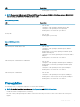
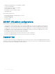
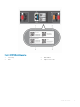


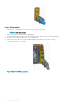

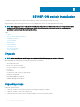
Table Of Contents
- S5148F-ON Installation Guide January 2019
- About this guide
- S5148F-ON switch
- Site preparations
- NEBS compliance
- S5148F-ON switch installation
- Power supplies
- Fans
- Management ports
- Specifications
- Chassis physical design
- IEEE standards
- Agency compliance
- USA Federal Communications Commission statement
- European Union EMC directive conformance statement
- Japan VCCI compliance for class A equipment
- Korean certification of compliance
- Safety standards and compliance agency certifications
- Electromagnetic compatibility
- Product recycling and disposal
- Dell EMC support

LED Description
• Flashing green—Port activity
NOTE: There are four LEDs for each SFP28 and QSFP28 port. For each port, 100GbE or 40GbE uses only one LED, 2x50GbE
uses two LEDs, and 4x25GbE or 4x10GbE uses all four LEDs.
Table 3. SFP28 port LEDs
LED Description
Link LED
• O—No link
• Solid green—Link operating at maximum speed, 10G
• Solid yellow—Link operating at a lower speed,1G
• Flashing yellow, 1 second on/o—port beacon
Activity LED
• O—No link
• Flashing green—port activity
Table 4. QSFP28 port LEDs
LED Description
Link/Activity LED—100G, 40G, or 10G
• O—No link
• Solid green—Link operating at maximum speed, 100G for
QSFP28 port
• Flashing green—Port activity operating at maximum speed,
100G for QSFP28 ports
• Solid yellow—Port activity operating at a lower speed, 40G or
10G port
• Flashing yellow, 1 second on/o—Port beacon
Link/Activity LED—4x25G mode or 4x10G mode
• O—No link
• Solid green—Link operating at maximum speed, 4x25G port
• Flashing green—Link activity operating at maximum speed,
4x25G port
• Solid yellow—Link operating at a lowr speed, 4x10G port
• Flashing yellow, 1 second on/o—Port beacon
Link/Activity LED—2x50G mode
• O—No link
• Solid yellow—Link operating at a lower speed, 2x50G port
• Flashing yellow—Port activity at a lower speed, 2x50G port
• Flashing yellow, 1 second on/o—Port beacon
Prerequisites
The following is a list of components required for successful switch installation:
NOTE
: For detailed installation instructions, see Site Preparations and S5148F-ON Installation.
• S5148F-ON switch or multiple switches, if stacking
• AC or DC country- and regional-specic cables to connect the AC or DC power source to each of the switches’ AC or DC power
supplies
S5148F-ON switch
11