
Install Guide
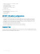
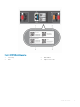


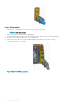

Table Of Contents
- S5148F-ON Installation Guide January 2019
- About this guide
- S5148F-ON switch
- Site preparations
- NEBS compliance
- S5148F-ON switch installation
- Power supplies
- Fans
- Management ports
- Specifications
- Chassis physical design
- IEEE standards
- Agency compliance
- USA Federal Communications Commission statement
- European Union EMC directive conformance statement
- Japan VCCI compliance for class A equipment
- Korean certification of compliance
- Safety standards and compliance agency certifications
- Electromagnetic compatibility
- Product recycling and disposal
- Dell EMC support
NEBS compliance
For your switch to be network equipment building system (NEBS) compliant, follow the instructions detailed in this section.
To be NEBS compliant, position your switch in the rack so that the air inlet is from the front aisle and the air exhaust is to the rear aisle.
Topics:
• Important information
• NEBS-compliant ground installation
Important information
WARNING: The SFP28, QSFP28, console, Ethernet management, and universal serial bus (USB) ports are suitable for
connection to intra-building or unexposed wiring or cabling only. You MUST NOT metallically connect the ports to interfaces that
connect to the out side plant (OSP) or its wiring. Use these interfaces as intrabuilding interfaces only (Type 2 or Type 4 ports as
described in GR-1089-CORE, Issue 6) and they require isolation from the exposed OSP cabling. Adding primary protectors is not
sucient protection to connect these interfaces metallically to OSP wiring.
WARNING: If you install and connect the S5148F-ON switch to a commercial AC power source, connect the switch to an
external special protection device (SPD).
To be NEBS compliant:
• Locate your switch in a restricted-access area were only trained personnel are allowed access.
• Install and connect your switch to the common bonding network (CBN).
• You can also install and connect your switch to the central oce.
• Connect the battery returns of your switch as DC-I.
• Ground your switch using a copper ground conductor.
• Clean and coat all bare grounding connection points on your switch with an antioxidant solution before making connections.
• Bring all unplated ground connection surfaces on your switch to a bright nish and treat them with an antioxidant solution before
making connections.
• To ensure electrical continuity, remove any nonconductive surfaces on your switch from the ground connection points and threaded
holes that secure the ground lugs.
• Use the two-hole, Listed, compression-type lug with an AWG 14 gauge wire for switch grounding.
NOTE
: The S5148F-ON switch can operate at -40.5 VDC to -60 VDC at a maximum current level of 24A.
NOTE: The S5148F-ON switch is Earthquake Z4-compliant when you attach the ReadyRails to the four-post frame using
threaded hardware. Do not use the tool-less or two-post installation methods.
NEBS-compliant ground installation
Before you install the switch into a rack, install the ground (GND) lug assembly.
Your switch includes an assembled UL-certied GND lug with bracket, packaged separately. If any parts are missing, contact your Dell EMC
Sales Representative.
4
NEBS compliance 17