
Install Guide
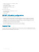
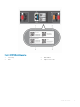


Table Of Contents
- S5148F-ON Installation Guide January 2019
- About this guide
- S5148F-ON switch
- Site preparations
- NEBS compliance
- S5148F-ON switch installation
- Power supplies
- Fans
- Management ports
- Specifications
- Chassis physical design
- IEEE standards
- Agency compliance
- USA Federal Communications Commission statement
- European Union EMC directive conformance statement
- Japan VCCI compliance for class A equipment
- Korean certification of compliance
- Safety standards and compliance agency certifications
- Electromagnetic compatibility
- Product recycling and disposal
- Dell EMC support
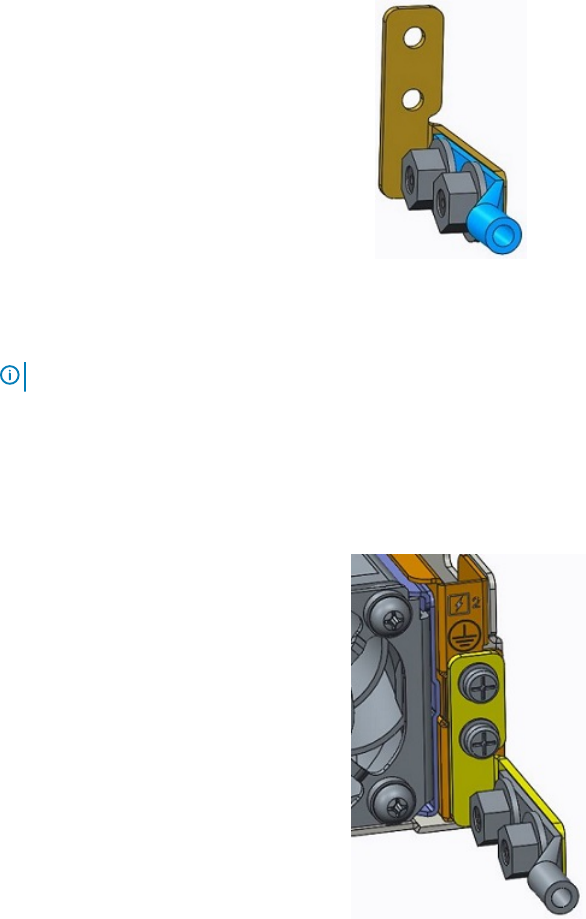
Figure 5. GND lug assembly
1 Remove the two installed M3 screws from the lower-left side of your switch.
NOTE: Keep these screws.
2 Remove the bracket assembly from the shipping bag.
3 Clean the bracket and lug surfaces thoroughly and apply an anti-oxidant solution to the mating surfaces.
4 Attach the switch ground using the Ground cable instructions.
5 Using the two removed screws, attach the GND lug bracket assembly to your switch, as shown.
Torque the M3 screws to ±4-5 in-lbs.
Figure 6. Attach the GND lug assembly
18
NEBS compliance