
Install Guide

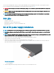


Table Of Contents
- S5148F-ON Installation Guide January 2019
- About this guide
- S5148F-ON switch
- Site preparations
- NEBS compliance
- S5148F-ON switch installation
- Power supplies
- Fans
- Management ports
- Specifications
- Chassis physical design
- IEEE standards
- Agency compliance
- USA Federal Communications Commission statement
- European Union EMC directive conformance statement
- Japan VCCI compliance for class A equipment
- Korean certification of compliance
- Safety standards and compliance agency certifications
- Electromagnetic compatibility
- Product recycling and disposal
- Dell EMC support
The PSUs have an integrated fan, which you cannot replace individually; if the fan integrated in a PSU fails, you must replace the entire
PSU. You can replace the fan trays individually. For fan tray replacement procedures, see Fans.
WARNING: Prevent exposure and contact with hazardous voltages. Do not attempt to operate this switch with the safety cover
removed.
CAUTION: Remove the power cable from the PSU before removing the PSU. Also, do not connect the power cable before you
insert the PSU in the switch.
NOTE: To comply with the GR-1089 Lightning Criteria for Equipment Interfacing with AC or DC Power Ports, use an external
surge protection device (SPD) at the AC or DC input of the router.
PSU LEDs
• Solid green—Input is OK.
• Flashing yellow—There is a fault with the PSU.
• Flashing green blink at 1Hz—Switch is in a standby/CR state.
• O—PSU is o.
AC or DC power supply installation
NOTE: The PSU slides into the slot smoothly. Do not force a PSU into a slot as this action may damage the PSU or the switch.
NOTE: Ensure that you correctly install the PSU. When you install the PSU correctly, the power connector is on the left side of
the PSU.
NOTE: If you use a single PSU, install a blank plate in the other PSU slot. If you are only using one power supply, install the power
supply in the rst slot, PSU1. Install a blank plate in the second slot, PSU2.
1 Remove the PSU slot cover from the S5148F-ON switch using a small #1 Phillips screwdriver.
2 Remove the PSU from the electro-static bag.
3 Insert the PSU into the switch PSU slot—insert the exposed PSU connector rst.
The PSU slot is keyed so that you can only fully insert the PSU in one orientation. When you install the PSU correctly, it snaps into
place and is ushed with the back of the switch.
Figure 16. PSU installation
• 1—PSU installation
4 Plug in the appropriate AC 3-prongs cord from the switch PSU to the external power source.
32
Power supplies