
Install Guide


Table Of Contents
- S5148F-ON Installation Guide January 2019
- About this guide
- S5148F-ON switch
- Site preparations
- NEBS compliance
- S5148F-ON switch installation
- Power supplies
- Fans
- Management ports
- Specifications
- Chassis physical design
- IEEE standards
- Agency compliance
- USA Federal Communications Commission statement
- European Union EMC directive conformance statement
- Japan VCCI compliance for class A equipment
- Korean certification of compliance
- Safety standards and compliance agency certifications
- Electromagnetic compatibility
- Product recycling and disposal
- Dell EMC support
5 Repeat steps 1 through 4 if you have a redundant PSU using the second PSU slot on the S5148F-ON switch.
NOTE: The S5148F-ON switch powers up when you connect the cables between the power supply and the power
source.
AC or DC power supply replacement
CAUTION: Disconnect the power cord before removing the power supplies. Also, disconnect all power cords before servicing.
NOTE: The PSU slides into the slot smoothly. Do not force a PSU into a slot as this action may damage the PSU or the S5148F-
ON switch.
NOTE: If a PSU fails, you must replace the entire unit. There are no eld serviceable components in the PSU. To request a
hardware replacement, see Dell EMC support.
NOTE: If you use a single PSU, install a blank plate in the other PSU slot. If you are only using one power supply, install the power
supply in the rst slot, PSU1. Install a blank plate in the second slot, PSU2.
1 Disconnect the power cable from the PSU.
2 Use the grab handle to slide the PSU out of the power supply bay.
3 Use the grab handle on the replacement PSU to slide it into the power supply bay.
4 Attach the power cord to the replacement PSU.
NOTE: The switch powers up when the cables are connected between the power supply and the power source.
DC power supply to power source connection
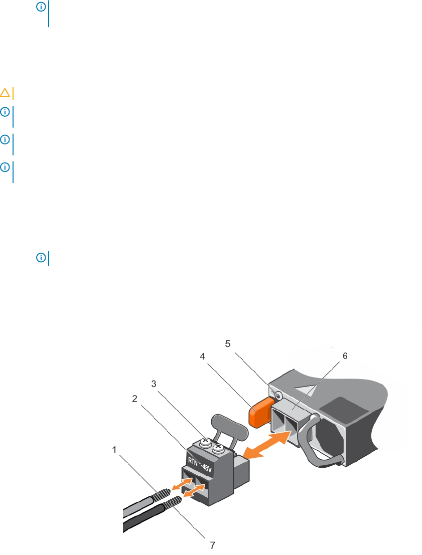
Each DC powered switch comes with a set containing a prewired, 3-inch 8 AWG, power supply connector and a four-screw wiring block.
One set is provided for each DC PSU.
Figure 17. DC power connector and wiring block
1
DC wire RTN 2 DC power connector
3 Captive screws (2) 4 Orange tab
5 PSU status LED 6 DC power socket
7 DC wire –48V
Power supplies 33