
Install Guide

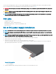


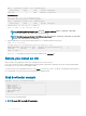
Table Of Contents
- S5148F-ON Installation Guide January 2019
- About this guide
- S5148F-ON switch
- Site preparations
- NEBS compliance
- S5148F-ON switch installation
- Power supplies
- Fans
- Management ports
- Specifications
- Chassis physical design
- IEEE standards
- Agency compliance
- USA Federal Communications Commission statement
- European Union EMC directive conformance statement
- Japan VCCI compliance for class A equipment
- Korean certification of compliance
- Safety standards and compliance agency certifications
- Electromagnetic compatibility
- Product recycling and disposal
- Dell EMC support

1 Strip 0.5 inches of insulation from each of the power connector’s wires, RTN and –48V.
2 Insert each of the power connector’s bare wire lengths into the wiring block. Insert RTN into one hole and –48V into the other hole.
3 Use a at-blade screwdriver to tighten the screws that secures the bare wires into the wiring block.
4 Secure the site’s DC power source wires to the other side of the wiring block, see steps 1 and 3.
WARNING: Do not cross the wires. In the wiring block, RTN aligns with RTN and –48V aligns with –48V.
5 Insert the DC power connector into the power socket of the DC PSU. Ensure that the connector pins rmly seat and you hear the
click of the power connector’s left and right levered clamps lock into place.
WARNING: Never try to force the power connector into or out of the DC PSU power socket.
NOTE: To remove the power connector from a DC PSU, use the orange tab on the side of the connector. Doing so disengages
the power connector’s clamps. After engaging the orange tab, pull the power connector from the DC PSU socket.
34 Power supplies