
Install Guide

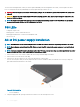


Table Of Contents
- S5148F-ON Installation Guide January 2019
- About this guide
- S5148F-ON switch
- Site preparations
- NEBS compliance
- S5148F-ON switch installation
- Power supplies
- Fans
- Management ports
- Specifications
- Chassis physical design
- IEEE standards
- Agency compliance
- USA Federal Communications Commission statement
- European Union EMC directive conformance statement
- Japan VCCI compliance for class A equipment
- Korean certification of compliance
- Safety standards and compliance agency certifications
- Electromagnetic compatibility
- Product recycling and disposal
- Dell EMC support
Fan LEDs
• Solid green—Fan function is normal.
• Flashing yellow—There is a fan fault.
• O—Fan is o.
Fan module installation
The fan modules in the S5148F-ON switch are eld replaceable. Module slot 1 is on the left side of the switch; module slot 4 is on the right
side of the switch.
CAUTION: DO NOT mix airow directions. All fans must use the same airow direction—reverse or normal. If you mix the airow
direction, to avoid damage to the switch,
you must correct the mixed airow
.
1 Take the fan module out of the shipping box.
2 Slide the module into the bay.
Figure 19. Fan module installation
• 1—Fan module
Fan module replacement
To request a hardware replacement, see Dell EMC support.
CAUTION
: Complete the following steps within one minute or the switch temperature could rise above safe thresholds and the
switch could shut down:
1 Slide the fan module out of the bay.
2 Slide the replacement module into the bay.
Fan air lter replacement
Environmental factors can decrease the amount of time required between air lter replacements. Check the environmental factors regularly.
An increase in temperature and/or particulate matter in the air might aect performance.
CAUTION
: Check the fan air lters at six-month intervals and replace them as necessary. To accurately determine air lter
replacement intervals, regularly monitor the speeds of the cooling fans. An increase in overall fan speed may indicate a clogged
lter.
36 Fans