
Install Guide


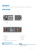
Table Of Contents
- S5148F-ON Installation Guide January 2019
- About this guide
- S5148F-ON switch
- Site preparations
- NEBS compliance
- S5148F-ON switch installation
- Power supplies
- Fans
- Management ports
- Specifications
- Chassis physical design
- IEEE standards
- Agency compliance
- USA Federal Communications Commission statement
- European Union EMC directive conformance statement
- Japan VCCI compliance for class A equipment
- Korean certification of compliance
- Safety standards and compliance agency certifications
- Electromagnetic compatibility
- Product recycling and disposal
- Dell EMC support
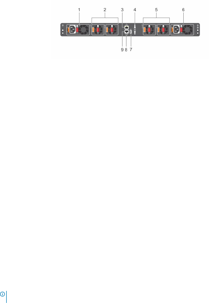
Figure 3. SS5148F-ON switch PSU-side view
1 PSU1 2 Fan Modules 1 and 2
3 RJ-45 management port 4 Luggage Tag
5 Fan Modules 3 and 4 6 PSU2
7 USB Type A 8 MicroUSB-B Port
9 RS-232 console port
Features
The S5148F-ON switch oers the following features:
• Forty-eight 10GbE and 25GbE SFP28 ports
• Six 40GbE and 100GbE QSFP28 ports
• One MicroUSB-B console port
• One RJ-45 serial console port
• One USB Type-A port for more le storage
• On-board Rangeley central processing unit (CPU) system with 8GB DDR III RAM, 16GB iSLC mSATA SSD
• One 10/100/1000BaseT Ethernet management port
• Two hot-swappable redundant power supplies
• Four hot-swappable fan modules
• Standard 1U switch
Physical dimensions
The S5148F-ON switch have the following physical dimensions:
• 434 x 462 x 44 mm (W x D x H)
• 17.1 x 18.2 x 1.72 inches (W x D x H)
• PSU/fan tray handle: 1.57 inches (40 mm)
LED display
The S5148F-ON switch includes LED displays on the I/O side of the switch.
NOTE
: If you are installing third-party software, for LED information, see your third-party operating software (OS)
documentation.
8 S5148F-ON switch