
Install Guide
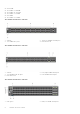
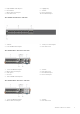
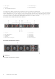
Table Of Contents
- Dell EMC PowerSwitch S5200F-ON Series Installation Guide August 2021
- Contents
- About this guide
- S5200F-ON Series switch
- Site preparations
- S5200F-ON Series switch installation
- Power supplies
- Fans
- Management ports
- Specifications
- Chassis physical design
- IEEE standards
- Agency compliance
- USA Federal Communications Commission statement
- European Union EMC directive conformance statement
- Japan VCCI compliance for class A equipment
- Korean certification of compliance
- Safety standards and compliance agency certifications
- Electromagnetic compatibility
- Product recycling and disposal
- Dell EMC support

5. USB Type A 6. RJ45 Ethernet port
7. DC PSUs 8. RJ45 console port
9. Three 100GbE QSFP28 ports
The S5212F-ON AC and DC switches have a reset button on the I/O-side below the Stack ID LED.
The S5200F-ON Series switch has one RJ45 serial console port, one Micro-USB type-B console port, one 10/100/1000 Base-T
Ethernet management port, one USB type-A port for the external storage, and for the S5212F-ON and S5296F-ON switches
only, one USB extension cable, which is packaged separately. Management ports are located on the PSU-side of the switch
except for the S5212F-ON switch that has the management ports on the I/O-side of the switch.
The S5232F-ON or S5248F-ON switch PSU-side view:
1. AC PSU1 2. Fan modules
3. RJ45 Ethernet port 4. USB Type A
5. Luggage tag 6. Fan modules
7. AC PSU2 8. Reset button
9. MicroUSB-B console port 10. RJ45 console port
The S5296F-ON switch PSU-side view:
1. Fan units
2. AC PSU units
The S5224F-ON switch PSU-side view:
10
S5200F-ON Series switch