
Install Guide
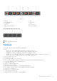
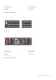
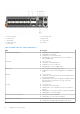
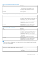
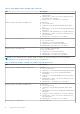
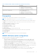
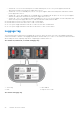
Table Of Contents
- Dell EMC PowerSwitch S5200F-ON Series Installation Guide August 2021
- Contents
- About this guide
- S5200F-ON Series switch
- Site preparations
- S5200F-ON Series switch installation
- Power supplies
- Fans
- Management ports
- Specifications
- Chassis physical design
- IEEE standards
- Agency compliance
- USA Federal Communications Commission statement
- European Union EMC directive conformance statement
- Japan VCCI compliance for class A equipment
- Korean certification of compliance
- Safety standards and compliance agency certifications
- Electromagnetic compatibility
- Product recycling and disposal
- Dell EMC support

1. Port Activity LED 2. Port Activity LED
3. Stack ID LED 4. Master LED
5. System LED 6. Locator LED
7. Link Activity LED 8. Fan LED
9. Power LED
Table 1. S5200F-ON Series switch LED behavior
LED Description
System Status/Health LED
● Solid green—Normal operation
● Flashing green—Booting
● Solid yellow—Critical system error
● Flashing yellow—Noncritical system error, fan failure, or
power supply failure
Power LED
● Off—No power
● Solid Green—Normal operation
● Solid yellow—POST is in process
● Flashing yellow—Power supply failed
Master LED
● Off—Switch is in Stacking Slave mode
● Solid green—Switch is in Stacking Master or Standalone
mode
FAN LED
● Off—No power
● Solid green—Normal operation; fan powered and running
at the expected RPM
● Flashing yellow—Fan fault—including incompatible airflow
direction when you insert the PSU or fan trays with
differing airflows
PSU LED
● Off—No power
● Solid green—Normal operation
● Flashing yellow—PSU warning event; power continues to
operate
● Flashing green—4Hz with five times on and off: Mismatch
● Flashing green—Firmware update
LOCATOR LED/System Beacon
● Off—Locator function disabled
● Flashing blue—Locator function enabled
7-Segment LED for stacking
● Off—No power
● Solid green—Hex digit representing the stack unit ID
16 S5200F-ON Series switch