
Install Guide
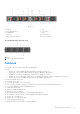
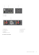
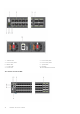
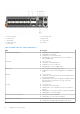
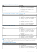
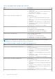
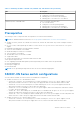
Table Of Contents
- Dell EMC PowerSwitch S5200F-ON Series Installation Guide August 2021
- Contents
- About this guide
- S5200F-ON Series switch
- Site preparations
- S5200F-ON Series switch installation
- Power supplies
- Fans
- Management ports
- Specifications
- Chassis physical design
- IEEE standards
- Agency compliance
- USA Federal Communications Commission statement
- European Union EMC directive conformance statement
- Japan VCCI compliance for class A equipment
- Korean certification of compliance
- Safety standards and compliance agency certifications
- Electromagnetic compatibility
- Product recycling and disposal
- Dell EMC support

Table 2. System management Ethernet port LEDs
LED Description
Link LED
● Off—No link
● Solid green—Link operating at a maximum speed,
autonegotiated/forced to 1000MBase-T mode
● Solid yellow—Link operating at a lower speed,
autonegotiated/forced or 10/100MBase-T mode
Activity LED
● Off—No activity
● Flashing green—Port activity
Table 3. SFP28 port LEDs—S5232F-ON, S5248F-ON, and S5296F-ON
LED Description
Link LED All four LEDs:
● Off—No link
● Solid green—Link operating at maximum speed, 25G
● Solid yellow—Link operating at a lower speed, 10G or 1G
● Flashing green, ~30ms—Port activity operating at
maximum speed, 25G port
● Flashing yellow, ~30ms—Port activity operating at lower
speed, 10G or 1G port
● Flashing yellow, 1 second on/off—port beacon
Activity LED
● Off—No activity
● Flashing green—port activity at maximum speed
● Flashing yellow—port activity at lower speed
Table 4. SFP+ port LEDs—S5232F-ON
LED Description
Link LED All four LEDs:
● Off—No link
● Solid green—Link operating at maximum speed, 10G
● Solid yellow—Link operating at a lower speed, 1G
● Flashing green, ~30ms—Port activity operating at
maximum speed, 10G port
● Flashing yellow, ~30ms—Port activity operating at lower
speed, 1G port
● Flashing yellow, 1 second on/off—port beacon
Activity LED
● Off—No activity
● Flashing green—port activity at maximum speed
● Flashing yellow—port activity at lower speed
NOTE: The first QSFP-DD port LED shows 200GbE, 100GbE, 40GbE, and 10GbE mode. All eight QSFP-DD port LEDs show
8x25GbE or 8x10GbE mode. The first and fifth QSFP-DD port LEDs show 2x100GbE mode. The first, second, fifth, and sixth
QSFP-DD port LEDs show 2x50GbE mode. The first and second LEDs for the first 2x50GbE port and the fifth and sixth
LEDs for the second 2x50GbE port.
Table 5. QSFP-DD port LEDs—S5248F-ON
LED Description
Link/Activity LED—200GbE, 100GbE, 40GbE, or 10GbE mode First LED:
● Off—No link/activity
● Solid green—Port link operating at maximum speed, 200G
● Flashing green—Port activity operating at maximum
speed, 200G
S5200F-ON Series switch 17