
Install Guide
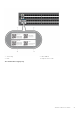
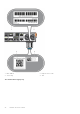
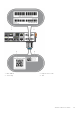
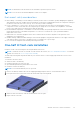
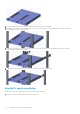
Table Of Contents
- Dell EMC PowerSwitch S5200F-ON Series Installation Guide August 2021
- Contents
- About this guide
- S5200F-ON Series switch
- Site preparations
- S5200F-ON Series switch installation
- Power supplies
- Fans
- Management ports
- Specifications
- Chassis physical design
- IEEE standards
- Agency compliance
- USA Federal Communications Commission statement
- European Union EMC directive conformance statement
- Japan VCCI compliance for class A equipment
- Korean certification of compliance
- Safety standards and compliance agency certifications
- Electromagnetic compatibility
- Product recycling and disposal
- Dell EMC support

NOTE: The illustrations in this document are not intended to represent a specific switch.
NOTE: Do not the use the mounted ReadyRails as a shelf or a workplace.
Rack mount safety considerations
● Rack loading—Overloading or uneven loading of racks may result in shelf or rack failure, possibly damaging the equipment
and causing personal injury. Stabilize racks in a permanent location before loading begins. Mount the components starting at
the bottom of the rack, then work to the top. Do not exceed your rack’s load rating.
●
Power considerations—Connect only to the power source specified on the unit. When you install multiple electrical
components in a rack, ensure that the total component power ratings do not exceed the circuit capabilities. Overloaded
power sources and extension cords present fire and shock hazards.
● Elevated ambient temperature—If installed in a closed rack assembly, the operating temperature of the rack environment
may be greater than the room ambient temperature. Use care not to exceed the 45°C (113°F) maximum ambient
temperature of the switch.
● Reduced air flow—Install the equipment in the rack so that the amount of airflow required for safe operation of the
equipment is not compromised.
● Reliable earthing—Maintain reliable earthing of rack-mounted equipment. Pay particular attention to the supply connections
other than the direct connections to the branch circuit, for example, use of power strips.
● Do not mount the equipment with the back panel facing downward.
One-half U front-rack installation
Install the S5212F-ON switch using the following installation instructions.
NOTE:
To install the S5232F-ON, S5248F-ON, and S5224F-ON switches, see One U ReadyRails installation. To install the
S5296F-ON switch, see Two U four-post rack assembly.
The dual-tray mounting rails ship with the dual tray, not with the switch. You must supply eight rackmount screws for this
installation.
To install the one-half U switch:
● Attach the rails to the dual tray.
● Install the dual tray in the four-post rack.
● (Recommended) Attach the ground cable to the switch.
● Install the switch in the dual tray.
NOTE: Do not install the dual tray in a two-post rack.
1. Remove the dual tray and the rails from the shipping packaging and place them on a clean antistatic surface.
2. Line up the three holes on the inner switch rail with the dual-tray mounting heads.
3. Attach the rail to the dual tray. Slide the rail back until it locks into place.
4. Repeat with the other side.
S5200F-ON Series switch installation
29