
Install Guide
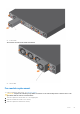
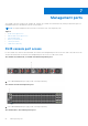
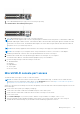
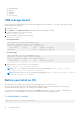
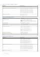
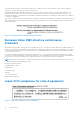
Table Of Contents
- Dell EMC PowerSwitch S5200F-ON Series Installation Guide August 2021
- Contents
- About this guide
- S5200F-ON Series switch
- Site preparations
- S5200F-ON Series switch installation
- Power supplies
- Fans
- Management ports
- Specifications
- Chassis physical design
- IEEE standards
- Agency compliance
- USA Federal Communications Commission statement
- European Union EMC directive conformance statement
- Japan VCCI compliance for class A equipment
- Korean certification of compliance
- Safety standards and compliance agency certifications
- Electromagnetic compatibility
- Product recycling and disposal
- Dell EMC support

1. Out-of-band management port (top); RS-232 console port (bottom)
The S5212F-ON DC switch management ports:
1. Out-of-band management port (top); RJ45 console port (bottom)
NOTE: When connecting the RJ45 console to the patch panel or terminal server using Cat5e or Cat6 Ethernet cables, the
maximum cable length is 100m. However, if the Ethernet cable is disconnected from the patch panel or terminal server but
connected to the RJ45 console, the maximum cable length is 6m. If the cable is longer than 6m when disconnected from
the panel or server, your switch may not boot.
NOTE: Ensure that any equipment that is attached to the serial port can support the required 115200 baud rate.
NOTE: If the serial port on your computer cannot accept a female DB-9 connector, use a DB-9 to USB adaptor.
1. Install the provided RJ45 connector-side of the provided cable into the switch console port.
2. Install the DB-9 female-side of the provided copper cable into the serial port on your computer.
Or install the DB-9 cable into other data terminal equipment (DTE) server hardware.
3. Use the following settings to make the serial port connection:
● 115200 baud rate
● No parity
● Eight data bits
● One stop bit
● No flow control
MicroUSB-B console port access
The MicroUSB-B console port is on the I/O side of the switch.
NOTE:
The S5200-ON Series switches use the Silicon Labs CP2102 USB-B chip. To find the correct USB-B universal
asynchronous receiver-transmitter (UART) driver, see the Downloads section of the https://www.silabs.com/products/
development-tools/software/usb-to-uart-bridge-vcp-drivers site.
When you connect the microUSB-B port, it becomes the primary connection and, while connected, all messages are sent to the
microUSB-B port.
1. Power on the client system (for example, your laptop).
2. Connect the USB-A end of cable into an available USB port on the client system.
3. Connect the microUSB-B end of cable into the microUSB-B console port on the switch.
4. Power on the switch.
5. Check Device Manager on your client system to find the com port number, for example, com 5 or 7 or 9.
6. Open your terminal software emulation program, such as Putty, to access the switch. Select the correct com port.
7. Confirm that the terminal settings on your terminal software emulation program are as follows:
Management ports
53