
Install Guide
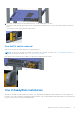
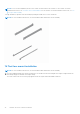
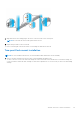
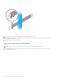
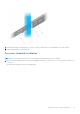
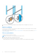
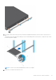
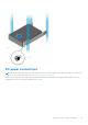
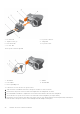
Table Of Contents
- Dell EMC PowerSwitch S5200F-ON Series Installation Guide January 2021
- About this guide
- S5200F-ON Series switch
- Site preparations
- S5200F-ON Series switch installation
- Power supplies
- Fans
- Management ports
- Specifications
- Chassis physical design
- IEEE standards
- Agency compliance
- USA Federal Communications Commission statement
- European Union EMC directive conformance statement
- Japan VCCI compliance for class A equipment
- Korean certification of compliance
- Safety standards and compliance agency certifications
- Electromagnetic compatibility
- Product recycling and disposal
- Dell EMC support

1. DC wire RTN 2. DC power connector
3. Captive screws (2) 4. Orange tab
5. PSU status LED 6. DC power socket
7. DC wire -48V
The DC power connector ground:
1.
Ground nut 2. Washer
3. Lock washer 4. Ground cable
5. Device grounding rod
To connect a DC PSU to the site’s DC power source:
1. Strip 1/2 inches of insulation from each of the power connector’s wires, as shown.
2. Insert each of the power connector’s bare wire lengths into the wiring block, as shown.
3. Use a flat-blade screwdriver to tighten the screws that secures the bare wires into the wiring block.
4. Secure the site’s DC power source wires to the other side of the wiring block (See steps 1 and 3).
5. Insert the DC power connector into the power socket of the DC PSU. Ensure that the connector pins firmly seat and you
hear the click of the power connector’s left and right levered clamps lock into place.
40
S5200F-ON Series switch installation