
Install Guide
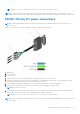
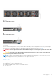
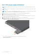
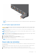
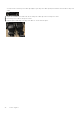
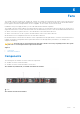
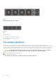
Table Of Contents
- Dell EMC PowerSwitch S5200F-ON Series Installation Guide January 2021
- About this guide
- S5200F-ON Series switch
- Site preparations
- S5200F-ON Series switch installation
- Power supplies
- Fans
- Management ports
- Specifications
- Chassis physical design
- IEEE standards
- Agency compliance
- USA Federal Communications Commission statement
- European Union EMC directive conformance statement
- Japan VCCI compliance for class A equipment
- Korean certification of compliance
- Safety standards and compliance agency certifications
- Electromagnetic compatibility
- Product recycling and disposal
- Dell EMC support

NOTE: Never try to force the power connector into or out of the DC PSU power socket.
NOTE: To remove the power connector from a DC PSU, squeeze the levers on both sides of the connector. Doing so
disengages the power connector’s clamps. While continuing to squeeze, pull the power connector from the DC PSU socket.
S5212F-ON only DC power connections
NOTE: Use the following instructions for the S5212F-ON switch only. For all other S5200F-ON Series switches, see DC
power connections.
Each DC PSU comes with a connector cable. One cable is provided for each DC PSU.
1. Wiring block
2. Power connector
3. PSU connector
1. Strip a 1/2 inch section of insulation from each of the power connector’s wires, as shown.
2. Insert each of the power connector’s bare wire lengths into the wiring block. The blue wire is -48V, the black wire is the
positive return, and the yellow/green wire is the ground wire, as shown.
3. Use a flat-blade screwdriver to tighten the screws that secures the bare wires into the wiring block.
4. Secure the site’s DC power source wires to the other side of the wiring block, see steps 1 and 3.
NOTE: Do not cross the wires.
5. Insert the DC power connector into the power socket of the DC PSU. Ensure that the connector pins firmly seat and you
hear the click of the power connector’s left and right levered clamps lock into place.
NOTE: Never try to force the power connector into or out of the DC PSU power socket.
NOTE: To remove the power connector from a DC PSU, unscrew the thumb screws and pull the power connector from the
DC PSU socket.
S5200F-ON Series switch installation 41