
Setup Guide
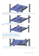
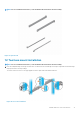
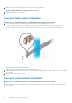
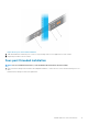
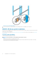
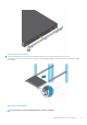
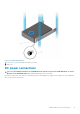
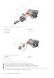

Figure 18. S5296F-ON installation
1. Extra screws to restrict front-back movement of the switch.
2. Main screw
DC power connections
NOTE:
Use the following instructions for all S5200F-ON Series switches except for the S5212F-ON switch. To connect
DC power to the S5212F-ON switch, see S5212F-ON only DC power connections.
Each DC powered system comes with a set containing a prewired (3-inch 8AWG) power supply connector and a four-screw wiring block.
One set is provided for each DC PSU.
S5200F-ON Series switch Installation
19