Dell EMC Networking OS10 Enterprise Edition Switch Configuration Guide for VxRail featuring S5248F-ON, S5232F-ON and S5148F-ON Deploying S5148F-ON switches for a VxRail 4.5 cluster and S5200F-ON switches for a VxRail 4.7.0 cluster. Abstract This document provides Dell EMC Networking OS10 Enterprise Edition switch configuration examples and topology options for a VxRail 4.5 cluster deployment using S5148F-ON. The document also includes a VxRail 4.7.0 cluster deployment using S5248F-ON and S5232F-ON.
Revisions Date Description November 2018 Added switch validation details for S5248F-ON and S5232F-ON with VxRail 4.7.0, port group and interface breakout information for S5248F-ON and S5232F-ON. September 2018 Initial release The information in this publication is provided “as is.” Dell Inc. makes no representations or warranties of any kind with respect to the information in this publication, and specifically disclaims implied warranties of merchantability or fitness for a particular purpose.
Table of contents Revisions............................................................................................................................................................................. 2 1 2 Introduction ................................................................................................................................................................... 6 1.1 Supported switches and operating systems ..............................................................................
7.1.1 General settings................................................................................................................................................23 7.1.2 Configure VLANs ..............................................................................................................................................24 7.1.3 Configure interfaces .........................................................................................................................................25 7.1.
C VxRail network adapter traffic optimization ................................................................................................................49 D Configure breakouts on port groups and interfaces ...................................................................................................50 D.1 Breakout port-groups for S5248F-ON ..............................................................................................................50 D.
1 Introduction VxRail sits at the forefront of a fundamental shift in IT infrastructure consumption – away from applicationspecific, “build-your-own” infrastructure and toward virtualized, general-purpose, engineered systems. Dell EMC and VMware have embraced this shift with the VxRail hyper-converged appliance. VxRail has a simple, scale-out architecture that leverages VMware vSphere and VMware vSAN to provide server virtualization and software-defined storage.
1.1 Supported switches and operating systems The examples provided in this deployment guide use VxRail 4.5 nodes connected to Dell EMC Networking S5148F-ON switches running Dell Networking OS10EE. This document also includes examples for S5248FON and S5232F-ON with VxRail 4.7.0. Dell EMC Networking supports the following switch and OS combinations for VxRail 4.
1.2 Typographical conventions The CLI and GUI examples in this document use the following conventions: 1.3 Monospace Text CLI examples Underlined Monospace Text CLI examples that wrap the page Italic Monospace Text Variables in CLI examples Bold Monospace Text Commands entered at the CLI prompt, or to highlight information in CLI output Bold text GUI fields and information entered in the GUI Attachments This document in .pdf format includes switch configuration file attachments.
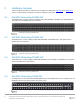
2 Hardware overview This section briefly describes the hardware used to validate this deployment. Appendix A and Appendix B contain a complete listing of hardware and software validated for this guide. 2.1 Dell EMC Networking S5248F-ON The S5248F-ON is a 1-Rack Unit (RU), multilayer switch with 48x25GbE, 4x100GbE, and 2x200GbE ports. This guide uses two S5248F-ONs as leaf switches. Dell EMC Networking S5248F-ON 2.
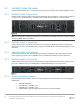
2.5 Dell EMC VxRail 14G nodes Current Dell EMC VxRail P, V, S, and E Series nodes are built on 14th generation (14G) PowerEdge servers. 2.5.1 Dell EMC VxRail P Series node VxRail P Series nodes are ideal for CPU-intensive workloads such as databases. P Series nodes support up to 44 CPU cores, 1536GB memory, and 24TB hybrid or 46TB all-flash storage in a 2-RU form factor.
Rear view of VxRail 2-RU node (1-RU node is similar) Note: Each of the VxRail P570 nodes in the deployment examples in this guide contains a Broadcom 57414 rNDC with 2x25GbE SFP28 ports. VxRail optimizes network traffic by splitting it across rNDC uplinks and by using Network I/O control (NIOC) shares for different traffic types. See Appendix C for more information. P, V, S, and E Series VxRail nodes also include a 1GbE BASE-T integrated Dell Remote Access Card (iDRAC) for OOB management.
3 Topology options VxRail may be deployed using a single or dual switch topology. Using a single switch provides the lowest initial cost but creates a single point of failure. A dual switch configuration helps ensure high availability by eliminating this single point of failure. A dual switch configuration may be used with or without VLT. Dell EMC recommends a dual switch configuration with VLT. The sections that follow explain the different options. 3.
• • • • Provides link-level resiliency Assures high availability Allows a single device to use a LAG across two upstream switches Provides Layer 2 multipathing Note: While VxRail nodes use active and standby network adapters instead of LAGs, other servers in the rack can connect to the VLT switch pair with an LACP LAG for active/active Layer 2 multipathing. For more information on VLT, see the OS10 Enterprise Edition User Guide Release 10.4.1.0. 3.1.
3.2 Single switch In a single switch topology, all VxRail nodes connect to a single switch. This topology is lower initial cost, but it is not recommended as the switch becomes a single point of failure.
4 VxRail in the data center 4.1 Leaf-spine network Dell EMC recommends using a leaf-spine network in the data center with leaf switches configured as VLT peers. The switches and VxRail nodes covered in this guide are shown in Rack 1 in Figure 12 and are incorporated into a data center’s leaf-spine network. Spine1 Spine2 Leaf-2A Leaf-2B L3 L2 L3 S5148F-Leaf1B S5148F-Leaf1A VLTi Leaf-nA Leaf-nB VLTi VLTi Additional VxRail clusters, servers, storage, etc.
4.2 OOB management network The out-of-band (OOB) management network is an isolated network for remote management of servers, switches, and storage devices via their dedicated hardware management ports. It is also commonly used to carry heartbeat messages sent between switches configured as VLT peers.
5 Configuration planning 5.1 VLANs and IP addresses VLANs and IP addresses used for VxRail node traffic must be planned before switch configuration and VxRail deployment can begin. VxRail node traffic is divided into four or more VLANs as shown in Table 1.
5.2 VxRail network configuration table Information provided in the VxRail network configuration table is used during VxRail deployment. The values used for this deployment example are shown in the right column. The VLANs and IP addresses used are based on the information from Table 2. Note: For additional information on the VxRail network configuration table, see the Dell EMC VxRail Network Guide.
Row 36 37 38 39 40 41 42 43 Category vSAN VM Networks … (unlimited number) Solutions Logging 44 45 Description Values used VLAN ID Starting address for IP pool Ending address for IP pool Subnet mask VLAN ID VM Network name and VLAN ID 1612 172.16.13.1 172.16.13.40 255.255.255.0 1613 VM_Network_A, 1614 VM Network name and VLAN ID vRealize Log Insight™ hostname VM_Network_B, 1615 vxinsight vRealize Log Insight IP address Syslog server (instead of Log Insight) 172.16.11.
An NTP server is not required but is recommended. If an NTP server is not provided, VxRail uses the time that is set on VxRail node 1. Note: For this deployment guide, the PowerEdge server used as the jump box also provides DNS and NTP services for the VxRail cluster. It is connected to both leaf switches for redundancy using Microsoft Windows NIC teaming (switch-independent load balancing).
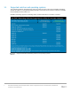
6 Switch configuration prerequisites 6.1 Check switch OS version S5148F-ON switches must be running OS10EE version 10.4.1.1 or later. Run the show version command to check the OS version. Dell EMC recommends upgrading to the latest release available on Dell Digital Locker (account required). OS10# show version S5148F-ON# show version Dell EMC Networking OS10-Enterprise Copyright (c) 1999-2018 by Dell Inc. All Rights Reserved. OS Version: 10.4.1.1 Build Version: 10.4.1.1.
6.3 Factory default configuration The configuration commands in the sections that follow begin with S5148F-ON switches at their factory default settings. Dell EMC Networking switches running OS10EE can be reset to their default configuration as follows: OS10# delete startup-configuration Proceed to delete startup-configuration [confirm yes/no(default)]:y OS10# reload System configuration has been modified.
7 Configure switches This section covers switch configuration for S5148F-ON switches in the different topologies. Commands for all examples are provided as attachments to this guide. 7.1 Dual switch with VLT This example uses a four-node VxRail cluster connected to a pair of switches configured with VLT as shown below. Dell EMC recommends using this topology.
Note: In OS10EE, LLDP is enabled on each interface and globally by default. LLDP is useful for troubleshooting and validation. Dell EMC recommends leaving it enabled. General settings – dual switch with VLT 7.1.2 S5148F-Leaf1A S5148F-Leaf1B configure terminal configure terminal hostname S5148F-Leaf1A hostname S5148F-Leaf1B interface mgmt1/1/1 no ip address ip address 100.67.172.38/24 no shutdown management route 0.0.0.0/0 100.67.172.254 interface mgmt1/1/1 no ip address ip address 100.67.172.
7.1.3 S5148F-Leaf1A S5148F-Leaf1B description VM_Network_B no shutdown description VM_Network_B no shutdown Configure interfaces Configure the interfaces for the jump box or laptop computer connections to be used during VxRail deployment. This example uses interface 1/1/9 on each switch. While only one connection is required, two are used for redundancy. Add these interfaces as access ports on VLAN 1611 (the in-band management VLAN).
7.1.
7.2 S5148F-Leaf1A S5148F-Leaf1B no shutdown no shutdown vlt-domain 127 backup destination 100.67.172.37 discovery-interface ethernet1/1/531/1/54 peer-routing vlt-domain 127 backup destination 100.67.172.38 discovery-interface ethernet1/1/531/1/54 peer-routing end write memory end write memory Dual switch without VLT This example uses a four-node VxRail cluster connected to a switch pair without VLT as shown below.
7.2.1 General settings Configure the hostname, OOB management IP address and default gateway. Specify an NTP server accessible by the switch. In this example, this is an NTP server on the OOB management network, with a different IP address than that used by the VxRail nodes on the in-band management network. Enable RSTP as a precaution against loops.
7.2.3 S5148F-Leaf1A S5148F-Leaf1B interface vlan1613 description vSAN no shutdown interface vlan1613 description vSAN no shutdown interface vlan1614 description VM_Network_A no shutdown interface vlan1614 description VM_Network_A no shutdown interface vlan1615 description VM_Network_B no shutdown interface vlan1615 description VM_Network_B no shutdown Configure interfaces Configure the interfaces for the jump box or laptop computer connections to be used during VxRail deployment.
7.2.
Configure switch interconnect - dual switch without VLT 7.
Note: The commands in the tables below should be entered in the order shown. All commands are provided in the file attachment named S5148F-single-switch.txt. 7.3.1 General settings Configure the hostname, OOB management IP address and default gateway. Specify an NTP server accessible by the switch. In this example, this is an NTP server on the OOB management network, with a different IP address than that used by the VxRail nodes on the in-band management network. Enable RSTP as a precaution against loops.
S5148F-ON description VM_Network_A no shutdown interface vlan1615 description VM_Network_B no shutdown 7.3.3 Configure interfaces Configure the interfaces for the jump box or laptop computer connections to be used during VxRail deployment. This example uses interfaces 1/1/9 and 1/1/10. While only one connection is required, two are used for redundancy. Add these interfaces as access ports on VLAN 1611 (the in-band management VLAN).
S5148F-ON switchport mode trunk switchport access vlan 1611 switchport trunk allowed vlan 1612-1615 spanning-tree port type edge flowcontrol receive on flowcontrol transmit on no shutdown interface ethernet1/1/18 description Node1_Port2 switchport mode trunk switchport access vlan 1611 switchport trunk allowed vlan 1612-1615 spanning-tree port type edge flowcontrol receive on flowcontrol transmit on no shutdown interface ethernet1/1/19 description Node2_Port1 switchport mode trunk switchport access vlan 161
S5148F-ON no shutdown interface ethernet1/1/23 description Node4_Port1 switchport mode trunk switchport access vlan 1611 switchport trunk allowed vlan 1612-1615 spanning-tree port type edge flowcontrol receive on flowcontrol transmit on no shutdown interface ethernet1/1/24 description Node4_Port2 switchport mode trunk switchport access vlan 1611 switchport trunk allowed vlan 1612-1615 spanning-tree port type edge flowcontrol receive on flowcontrol transmit on no shutdown end write memory 35 Dell EMC Netwo
8 Switch validation After switches are configured and devices are connected, the switch CLI is used to validate the network configuration. This section provides a list of the most common commands and their output for the examples used in this guide. 8.1 General validation commands The commands and output shown below are for S5148F-Leaf1A in the dual switch with VLT topology. The output of its peer, S5148F-Leaf1B, is similar.
Note: The command output for the dual switch without VLT topology is shown below. In this example, Port channel 127 is up (U) and DYNAMIC indicates LACP is used. Ports 1/1/53 and 1/1/54 are port channel members and (P) indicates each is up and active.
Note: For the dual switch without VLT topology, the VLAN portion of the command output is as follows: NUM Status Description 1 Active 1/1/16,1/1/21-1/1/52 1611 Active InBand_Mgmt 1612 Active vMotion 1613 Active vSAN 1614 Active VM_Network_A 1615 Active VM_Network_B Q Ports A Eth1/1/1-1/1/8,1/1/10A T A T T T T T T T T Po127 Po127 Eth1/1/9,1/1/17-1/1/20 Eth1/1/17-1/1/20 Po127 Eth1/1/17-1/1/20 Po127 Eth1/1/17-1/1/20 Po127 Eth1/1/17-1/1/20 Po127 For the single switch topology, the VLAN portion
8.1.5 show vrrp brief In this deployment, VRRP is configured on the in-band management VLAN, 1611, to provide gateway redundancy for management traffic. The output from the show vrrp brief command shows the master and virtual IP addresses and whether the switch is in the master or backup role. The switch configured with the largest priority value, shown in the Priority column, becomes the master.
VLT Backup Link -----------------------Destination Peer Heartbeat status Heartbeat interval Heartbeat timeout 8.2.3 : : : : 100.67.172.37 Up 30 90 show vlt domain_id mismatch This command highlights any potential configuration issues between VLT peers. All items must indicate No mismatch.
9 Deploy VxRail A laptop computer or jump box with a web browser for the VxRail user interface is required. It is either plugged into a leaf switch or able to logically reach the VxRail in-band management VLAN from elsewhere on the network. By default, the initial VxRail Manager IP address is 192.168.10.200/24. After initial configuration, the address changes to its new address on the in-band management network. The new VxRail Manager address used in this guide is 172.16.11.
In a web browser on the laptop computer or jump box, connect to https://192.168.10.200 and deploy VxRail using the planning data in Table 3. Note: VxRail installation steps are beyond the scope of this guide.
10 Use of VxRail 4.7.0 to validate Dell EMC Networking S5200F-ON With VxRail 4.7.0, two in-band management networks are used - public and private. In this example, VLAN 3939 serves as the default VLAN for the VxRail private management network, and VLAN 1611 remains as the public in-band management network. The Node discovery network is isolated to VLAN 3939. The Leaf switches must be configured appropriately for the changes to be incorporated. VxRail 4.7 Prior to VxRail 4.
Note: See attachment for S5200-ON switch configurations for single ToR switch, leaf switches in VLT and leaf switches in port channel. Note: To configure breakouts on S5248F-ON port groups or 5232F-ON interfaces, see Appendix D.
A Validated components for S5148F-ON using VxRail 4.5 The following tables include the hardware, software, and firmware used to configure and validate the examples in this guide. A.1 Dell EMC Networking Switches Switches and OS versions A.2 Qty Item OS Version 2 Dell EMC Networking S5148F-ON leaf switches 10.4.1.1 1 Dell EMC Networking S3048-ON management switch 10.4.1.1 DAC Cables DAC cables used to connect nodes to ToR Qty Item DP/N 8 DAC-SFP28-25G-3.
A.4 VxRail Appliance software The examples using S5148F-ON in this guide were developed using VxRail Appliance software 4.5.200. It consists of the component versions shown below. VxRail Appliance software component versions 46 Item Version VxRail Manager 4.5.200.7769314 VMware ESXi 6.5.0 Update 1 Patch 36, build 7388607 VMware vCenter Server Appliance 6.5 Update 1e, build 7515524 VMware vSAN 6.6.1 Patch 02 VMware vRealize Log Insight 4.
B Validated components for S5248F-ON and S5232F-ON using VxRail 4.7.0 The tables that are provided in Appendix B include hardware, software, and firmware that is used to configure and validate the examples in this guide. B.1 Dell EMC Networking switches Switches and operating systems versions B.2 Qty Item operating systems version Build version 2 Dell EMC Networking S5248F-ON leaf switches 10.4.2.0 10.4.2.0.63 2 Dell EMC Networking S5232F-ON leaf switches 10.4.2.0 10.4.2.0.
B.4 VxRail appliance software Chapter 10 of this deployment guide was developed using VxRail appliance software 4.7.0. The software consists of the component versions that are provided below: VxRail appliance software component versions 48 Item Version VxRail Manager 4.7.000 10378475 VMware ESXi 6.7.0 build 10302608 VMware vCenter Server Appliance 6.7.0 build 10244857 VMware vSAN vSAN 6.7 Update 1 VMware vRealize Log Insight 4.6.
C VxRail network adapter traffic optimization VxRail optimizes network traffic by splitting traffic across rNDC uplinks and by using NIOC shares. Based on traffic type, uplinks are configured as active or standby, and NIOC shares are used to allocate network bandwidth. Uplink load balancing and NIOC shares are automatically configured by VxRail.
D Configure breakouts on port groups and interfaces The configuration of breakouts on port groups on S5248F-ON and interfaces on S5232F-ON allows the Ethernet ports to be broken into the desired configuration. D.1 Breakout port-groups for S5248F-ON The ports on the S5248F-ON are grouped into port groups, where each port group has an associated breakout mode. For example, port group 1/1/2 has a breakout mode set to four 25GbE ports. Ports 5, 6, 7 and 8 are included in this port group.
D.2 Breakout interfaces for S5232F-ON The S5232F-ON provides 100GbE ports that can be broken into interface(s) with different speeds. The command options include: • • • • • 100g-1x Breakout to 1x100G interface 50g-2x Breakout to 2x50G interfaces 40g-1x Breakout to 1x40G interface 25g-4x Breakout to 4x25G interfaces 10g-4x Breakout to 4x10G interfaces To configure a breakout for an interface, use the interface breakout command.
E Technical resources Dell EMC Networking Guides OS10 Enterprise Edition User Guide Release 10.4.1.0 OS10 Enterprise Edition User Guide Release 10.4.2.
F Support and feedback Contacting Technical Support Support Contact Information Web: http://www.dell.com/support Telephone: USA: 1-800-945-3355 Feedback for this document We encourage readers to provide feedback on the quality and usefulness of this publication by sending an email to Dell_Networking_Solutions@Dell.com.