Dell EMC PowerSwitch S5200F-ON Series Installation Guide January 2021 January 2021 Rev.
Notes, cautions, and warnings NOTE: A NOTE indicates important information that helps you make better use of your product. CAUTION: A CAUTION indicates either potential damage to hardware or loss of data and tells you how to avoid the problem. WARNING: A WARNING indicates a potential for property damage, personal injury, or death. © 2018 - 2021 Dell Inc. or its subsidiaries. All rights reserved. Dell, EMC, and other trademarks are trademarks of Dell Inc. or its subsidiaries.
Contents Chapter 1: About this guide........................................................................................................... 5 Related documents............................................................................................................................................................. 5 Information symbols............................................................................................................................................................
After switch placement....................................................................................................................................................42 Switch replacement.......................................................................................................................................................... 43 Chapter 5: Power supplies...........................................................................................................44 Components..................
1 About this guide This guide provides site preparation recommendations, step-by-step procedures for rack mounting and desk mounting your switch, inserting modules, and connecting to a power source. CAUTION: To avoid electrostatic discharge (ESD) damage, wear grounding wrist straps when handling this equipment. NOTE: Only trained and qualified personnel can install this equipment. Read this guide before you install and power up this equipment. This equipment contains two power cords.
Information symbols This book uses the following information symbols: NOTE: The Note icon signals important operational information. CAUTION: The Caution icon signals information about situations that could result in equipment damage or loss of data. NOTE: The Warning icon signals information about hardware handling that could result in injury. NOTE: The ESD Warning icon requires that you take electrostatic precautions when handling the device.
2 S5200F-ON Series switch The following sections describe the Dell EMC S5200F-ON Series (S5232F-ON, S5248F-ON, S5296F-ON, S5224F-ON, and S5212F-ON) switch: Topics: • • • • • • • Introduction Features Physical dimensions LED display Prerequisites S5200F-ON Series switch configurations Luggage tag Introduction The S5200F-ON Series (S5232F-ON, S5248F-ON, S5296F-ON, S5224F-ON, and S5212F-ON) switch is a full-featured fixed form-factor top-of-rack (ToR) compact 10/25/40/50/100/200GbE switch for data center ne
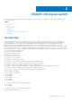
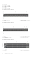
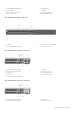
● ● ● ● ● ● 24 X 25GbE 12 x 10GbE + 3 x 100GbE 12 x 10GbE + 12 x 25 GbE 12 x 25GbE + 3 x 40GbE 24 x 10GbE 12 x 25GbE + 6 x 50GbE The S5232F-ON switch I/O-side view: 1. Stack ID 3. Two 10GbE SFP+ ports 2. Thirty-two 100GbE QSFP28 ports 4. LED Status Icons The S5248F-ON switch I/O-side view: 1. Stack ID 3. Two 200GbE QSFP-DD ports 5. LED status icons 2. Forty-eight 25GbE SFP28 ports 4. Four 100GbE QSFP28 ports The S5296F-ON switch I/O-side view: 1. USB Type A 8 S5200F-ON Series switch 2.
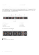
3. 5. 7. 9. Eight 100GbE QSFP28 ports Reset button MicroUSB-B console port LED status icons 4. 6. 8. 10. Luggage tag Stack ID RJ45 console port RJ45 Ethernet port The S5224F-ON switch I/O-side view: 1. Stack ID 3. Four 100GbE QSFP28 ports 2. Twenty-four SFP28 ports 4. LED status icons The S5212F-ON AC switch I/O-side view: 1. 3. 5. 7. 9. Twelve 25GbE SFP28 ports MicroUSB-B console port USB Type A AC PSUs Three 100GbE QSFP28 ports 2. 4. 6. 8.
5. USB Type A 7. DC PSUs 9. Three 100GbE QSFP28 ports 6. RJ45 Ethernet port 8. RJ45 console port The S5212F-ON AC and DC switches have a reset button on the I/O-side below the Stack ID LED. The S5200F-ON Series switch has one RJ45 serial console port, one Micro-USB type-B console port, one 10/100/1000 Base-T Ethernet management port, one USB type-A port for the external storage, and for the S5212F-ON and S5296F-ON switches only, one USB extension cable, which is packaged separately.
1. 3. 5. 7. 9. AC PSU RJ45 Ethernet port Luggage tag AC PSU MicroUSB-B console port 2. 4. 6. 8. 10. Fans USB Type A Fans Reset button RJ45 console port The S5212F-ON switch PSU-side view: 1. Fans 2.
● S5212F-ON and S5296F-ON—USB male-female extension cable ● Switch: ○ S5212F-ON—Standard one-half rack unit ○ S5224F-ON—Standard one rack unit ○ S5232F-ON—Standard one rack unit ○ S5248F-ON—Standard one rack unit ○ S5296F-ON—Standard two rack units Physical dimensions The S5200F-ON Series switch have the following physical dimensions: ● S5212F-ON—one-half rack unit: ○ 7.87 x 16 x 1.72 inches (W x D x H) ○ 199.8 x 406.4 x 43.6 mm (W x D x H) ● S5224F-ON, S5232F-ON, S5248F-ON—one rack unit: ○ 17.1 x 18.
1. 3. 5. 7. 9. Stack ID LED Port Activity LED System LED Fan LED RJ45 Ethernet Port LED 2. 4. 6. 8.
1. 3. 5. 7. 9. Stack ID LED Port Activity LEDs Master LED Locator LED Power LED The S5296F-ON switch LEDs: 14 S5200F-ON Series switch 2. 4. 6. 8. 10.
1. 3. 5. 7. Stack ID LED Port Activity LEDs System LED Fan LED 2. 4. 6. 8. Port Activity LEDs Port Activity LEDs Locator LED Power LED 2. 4. 6. 8. Port Activity LED Master LED Locator LED Power LED The S5224F-ON switch LEDs: 1. 3. 5. 7. 9.
1. 3. 5. 7. 9. Port Activity LED Stack ID LED System LED Link Activity LED Power LED 2. 4. 6. 8. Port Activity LED Master LED Locator LED Fan LED Table 1.
Table 2. System management Ethernet port LEDs LED Description Link LED ● Off—No link ● Solid green—Link operating at a maximum speed, autonegotiated/forced to 1000MBase-T mode ● Solid yellow—Link operating at a lower speed, autonegotiated/forced or 10/100MBase-T mode Activity LED ● Off—No activity ● Flashing green—Port activity Table 3.
Table 5.
Table 6.
● ● ● ● ○ S5224F-ON—one U, 24 x 25G SFP28 ports, 4 x 100G QSFP28 ports, two AC or DC power supplies, and four fan subsystems with airflow from the power supply side to the I/O ○ S5232F-ON—one U, 32 x 100GbE ports, two AC or DC power supplies, and four fan subsystems with airflow from the power supply side to the I/O ○ S5248F-ON— one U, 48 x 25GbE ports, 4 x 200GbE ports, 2 x 200GbE QSFP-DD ports, two AC or DC power supplies, and four fan subsystems with airflow from the power supply side to the I/O ○ S5296
1. Service tag 3. PPID 2. MAC address 4.
1. MAC address 3. Service tag The S5212F-ON DC luggage tag: 22 S5200F-ON Series switch 2. Express service code 4.
1. MAC address 3. Service tag 2. Express service code 4.
3 Site preparations The S5200F-ON Series (S5232F-ON, S5248F-ON, S5296F-ON, S5224F-ON, and S5212F-ON) switch is suitable for installation as part of a common bond network (CBN). You can install the switch in: ● Network telecommunication facilities ● Data centers ● Other locations where the National Electric Code (NEC) applies NOTE: Install the switch into a rack or cabinet before installing any additional components such as cables or optics.
Rack mounting When you prepare your equipment rack, ensure that the rack is grounded. Ground the equipment rack to the same ground point the power service in your area uses. The ground path must be permanent. Switch ground Dell EMC recommends you ground your switch. Use the S5200F-ON Series switch in a common bond network (CBN). Connect the grounding cables as described in S5200F-ON Series switch installation.
Storing components If you do not install your S5200F-ON Series switch and components immediately, properly store the switch and all components using these guidelines: ● Storage location temperature must remain constant. The storage range is from -40°C to 70°C (-40° to 158°F). ● Store on a dry surface or floor, away from direct sunlight, heat, and air conditioning ducts. ● Store in a dust-free environment. NOTE: ESD damage can occur when components are mishandled.
4 S5200F-ON Series switch installation To install the S5200F-ON Series (S5232F-ON, S5248F-ON, S5296F-ON, S5224F-ON, and S5212F-ON) switch, complete the installation procedures in the order presented in this chapter. Always handle the switch and components with care. Avoid dropping the switch or its field replaceable units (FRUs). For the S5212F-ON switch installation instructions, see One-half U front-rack installation.
● Use the two-hole, Listed, compression-type lug with an AWG 14 gauge wire for switch grounding. ● Dell Technologies recommends changing the front air filter every three months, depending on the switch environment (if applicable). NOTE: If you install and connect the switches to a commercial AC power source, you must connect the switch to an external surge protection device (SPD).
NOTE: The illustrations in this document are not intended to represent a specific switch. NOTE: Do not the use the mounted ReadyRails as a shelf or a workplace. Rack mount safety considerations ● Rack loading—Overloading or uneven loading of racks may result in shelf or rack failure, possibly damaging the equipment and causing personal injury. Stabilize racks in a permanent location before loading begins. Mount the components starting at the bottom of the rack, then work to the top.
5. Install the dual tray inside the four-post rack. Rackmount screws are not included. 6. Attach the front dual-tray switch rails to the four-post rack from the front. Secure the dual tray to the rack using two user-supplied screws for each rack post. 7. Attach the rear dual-tray switch rails to the four-post rack from the rear. Secure the dual tray to the rack using two user-supplied screws for each rack post. 8. Tighten all mounting screws to securely mount the dual tray into the four-post rack.
2. Insert the second switch in the open dual-tray slot if you are installing two switches. The switch is fully inserted when it presses the stop features on the dual tray. The front switch latch snaps the switch into place. Close-up view of the stop at the back of the switch. One-half U switch removal Remove the S5212F-ON switch using the following instructions: NOTE: To remove the S5232F-ON, S5248F-ON, S5296F-ON, or S5224F-ON switch, see One U ReadyRails installation.
NOTE: Do not use the ReadyRails system for the S5212F-ON and S5296F-ON switches. For the S5212F-ON switch installation instructions, see One-half U front-rack installation. For the S5296F-ON switch installation instructions, see Two U four-post rack assembly. To begin installation, separate each rail assembly by sliding the inside rail out of the outside rail. NOTE: For more installation instructions, see the installation labels attached to the rail assembly.
2. Align and seat the front flange pegs in the holes on the front side of the vertical post. NOTE: Be sure that the rails click into place and are secure. 3. Repeat this procedure for the second rail. To remove each rail, pull on the latch release on each flange ear and unseat each rail. Two-post flush-mount installation NOTE: For more installation instructions, see the installation labels attached to the rail assembly. 1. Remove the latch castings from the front side of each ReadyRails assembly, item 1.
2. Attach one rail to the front post flange with two user-supplied screws, item 2. 3. Slide the plunger bracket forward against the vertical post and secure the plunger bracket to the post flange with two user-supplied screws, item 3. 4. Repeat this procedure for the second rail. Two-post center-mount installation NOTE: For more installation instructions, see the installation labels attached to the rail assembly. 1.
2. Slide the back bracket towards the post. Secure it to the post flange with two user-supplied screws, items 2 and 3. 3. Repeat this procedure for the second rail. Four-post threaded installation NOTE: For more installation instructions, see the installation labels attached to the rail assembly. 1. Remove the latch castings from each end of the ReadyRails assemblies. To remove the two screws each latch casting, use a Torx driver. Retain the latch castings for future rack requirements.
2. For each rail, attach the front and back flanges to the post flanges with two user-supplied screws at each end. Switch installation For the 1U two-post configurations for the S5224F-ON, S5248F-ON, and S5232F-ON switches, slide the switch into the rails in the same manner as the four-post configurations. For the S5212F-ON switch installation, see One-half U front-rack installation. For the S5296F-ON switch installation, see Two U four-post rack assembly.
2. Line up both switch rails with the previously mounted rack ReadyRails and slide the switch in until it is flush with front of rack. To keep the switch from inadvertently sliding out of the rack and falling, about 3 inches before you fully insert your switch, the rail locking feature engages. NOTE: Do not the use the mounted ReadyRails as a shelf or a workplace. 3. Tighten the two thumbscrews and rack screws.
To remove the switch from the rack or cabinet, press in the two side-release bars on the switch simultaneously and slide the switch forward. Two U four-post rack assembly Due to the chassis weight, the S5296F-ON switch does not support a two-post rack installation; you must install the S5296FON in a four-post rack. NOTE: To install the S5212F-ON switch, see One-half U front-rack installation. To install the S5224F-ON, S5232F-ON, or S5248F-ON, switch see, One U ReadyRail installation.
DC power connections NOTE: Use the following instructions for all S5200F-ON Series switches except for the S5212F-ON switch. To connect DC power to the S5212F-ON switch, see S5212F-ON only DC power connections. Each DC powered system comes with a set containing a prewired (3-inch 8AWG) power supply connector and a four-screw wiring block, as shown. One set is provided for each DC PSU.
1. 3. 5. 7. DC wire RTN Captive screws (2) PSU status LED DC wire -48V 2. DC power connector 4. Orange tab 6. DC power socket The DC power connector ground: 1. Ground nut 3. Lock washer 5. Device grounding rod 2. Washer 4. Ground cable To connect a DC PSU to the site’s DC power source: 1. Strip 1/2 inches of insulation from each of the power connector’s wires, as shown. 2. Insert each of the power connector’s bare wire lengths into the wiring block, as shown. 3.
NOTE: Never try to force the power connector into or out of the DC PSU power socket. NOTE: To remove the power connector from a DC PSU, squeeze the levers on both sides of the connector. Doing so disengages the power connector’s clamps. While continuing to squeeze, pull the power connector from the DC PSU socket. S5212F-ON only DC power connections NOTE: Use the following instructions for the S5212F-ON switch only. For all other S5200F-ON Series switches, see DC power connections.
Optics installation The S5200F-ON Series (S5232F-ON, S5248F-ON, S5296F-ON, S5224F-ON, and S5212F-ON) switches have SFP+, SFP28, QSFP-DD, and QSFP28 optical ports. For a list of supported optics, see the specification sheets at www.dell.com/support or contact your Dell EMC Sales representative. CAUTION: ESD damage can occur if components are mishandled. Always wear an ESD-preventive wrist or heel ground strap when handling the S5200F-ON Series switch and components.
● For OS10 Networking operating system documentation and resources, see the Dell EMC Networking OS10 Info Hub. ● For ONIE documentation and resources, see ONIE information at www.onie.org. Switch replacement The following steps describe removing and replacing a switch with an identical replacement switch. For further assistance when replacing a switch, contact your Dell EMC support representative. NOTE: Some steps do not apply if you are replacing a different switch or non-Dell EMC switch.
5 Power supplies The S5200F-ON Series (S5232F-ON, S5248F-ON, S5296F-ON, S5224F-ON, or S5212F-ON) switch ships with two AC or DC power supplies. The two power supplies have two air-flow directions—from the I/O to the PSU and from the PSU to the I/O. Two PSUs are required for full redundancy, but the switch can operate with a single PSU. For all switches except the S5212F-ON switch, the PSUs are field replaceable.
The S5296F-ON PSUs: 1. PSUs The S5212F-ON AC PSUs: 1. AC PSUs The S5212F-ON DC PSUs: 1. DC PSUs The PSUs have an integrated fan, which you cannot replace individually; if the fan integrated in a PSU fails, you must replace the entire PSU. You can replace the fan trays individually. For fan tray replacement procedures, see Fans. WARNING: Prevent exposure and contact with hazardous voltages. Do not attempt to operate this switch with the safety cover removed.
AC or DC power supply installation NOTE: The PSU slides into the slot smoothly. Do not force a PSU into a slot as this action may damage the PSU or the switch. NOTE: Ensure that you correctly install the PSU. When you install the PSU correctly, the power connector is on the left side of the PSU. NOTE: If you use a single PSU, install a blank plate in the other PSU slot. If you are only using one power supply, install the power supply in the first slot, PSU1. Install a blank plate in the second slot, PSU2.
● 1--PSU NOTE: The S5200F-ON Series switch starts up when you connect the cables between the power supply and the power source. AC or DC power supply replacement CAUTION: Disconnect the power cable before removing the power supplies. Also, disconnect all power cables before servicing. NOTE: The PSU slides into the slot smoothly. Do not force a PSU into a slot as this action may damage the PSU or the S5200F-ON Series switch. NOTE: If a PSU fails, you must replace the entire unit.
You may need to twist the power cable clip slightly to get the power cable clip fully inserted into the holes above the power outlet. 3. Repeat the installation procedure with the second power cable clip on the second power outlet. 4. Insert the power cords into the power outlets. 5. Push the power cable clips over the power cables to secure them into place.
6 Fans The S5200F-ON Series (S5232F-ON, S5248F-ON, S5296F-ON, S5224F-ON, and S5212F-ON) switch comes from the factory with two PSUs and four fan modules installed in the switch. For all switches except the S5212F-ON, the fan modules and the power supplies, which have integrated fans, are hot-swappable. For the S5212F-ON, the fans are fixed. In addition to the power supply modules, you can order and install fan modules separately. The S5200F-ON Series switch supports two airflow direction options.
1. Fans The S5212F-ON switch fan modules: 1. Fans Fan LEDs ● Solid green—Fan function is normal. ● Flashing yellow—There is a fan fault. ● Off—Fan is off. Fan module installation For all switches except the S5212F-ON, the fan modules in the S5200F-ON Series switch are field replaceable. For the S5212F-ON switch, the fans are fixed.
● 1—fan module The S5296F-ON switch fan module installation: ● 1--fan module Fan module replacement To request a hardware replacement, see Dell EMC support. CAUTION: Complete the following steps within one minute or the switch temperature could rise above safe thresholds and the switch could shut down: 1. Take the replacement fan module out of the shipping box. 2. Slide the installed fan module out of the bay. 3. Slide the replacement module into the bay.
7 Management ports The S5200F-ON Series (S5232F-ON, S5248F-ON, S5296F-ON, S5224F-ON, and S5212F-ON) switch provides three ports for management and one USB flash drive mount for file transfers. NOTE: The output examples in this section are for reference only. Your output may vary.
1. Out-of-band management port (top); RS-232 console port (bottom) The S5212F-ON DC switch management ports: 1. Out-of-band management port (top); RJ45 console port (bottom) NOTE: When connecting the RJ45 console to the patch panel or terminal server using Cat5e or Cat6 Ethernet cables, the maximum cable length is 100m. However, if the Ethernet cable is disconnected from the patch panel or terminal server but connected to the RJ45 console, the maximum cable length is 6m.
5. Install the necessary USB device drivers. To download Dell EMC drivers, see www.dell.com/support. If your computer requires non-Dell EMC drivers, contact Dell EMC Technical Support for assistance. 6. Open your terminal software emulation program to access the switch. 7. Confirm that the terminal settings on your terminal software emulation program are as follows: ● ● ● ● ● 115200 baud rate No parity 8 data bits 1 stop bit No flow control USB storage mount USB storage does not automatically mount.
Grub bootloader example GNU GRUB version 2.02~beta2+e4a1fe391 +-------------------------------------------------+ |*ONIE: Install OS | | ONIE: Rescue | | ONIE: Uninstall OS | | ONIE: Update ONIE | | ONIE: Embed ONIE | | EDA-DIAG | | | +-------------------------------------------------+ Your switch comes with ONIE installed. NOTE: To access ONIE, use the RJ45 or MicroUSB console port.
00:14.1 Class 0200: 8086:1f41 00:14.2 Class 0200: 8086:1f41 00:16.0 Class 0c03: 8086:1f2c 6:1f22 lass 0106: 8086:1f32 00:1f.0 Class 0601: 8086:1f38 00:1f.3 Class 0c05: 8086:1f3c 01:00.0 Class 0200: 14e4:b960 (NPU PCI detection) 01:00.1 ONIE:/ # ONIE service discovery ONIE attempts to locate the installer through several discovery methods. To download and run an installer, the ONIE Service Discovery feature follows these steps in order and uses the first successful method found: 1.
8 Specifications This section lists the S5200F-ON Series (S5232F-ON, S5248F-ON, S5296F-ON, S5224F-ON, and S5212F-ON) switch specifications. CAUTION: Operate the product at an ambient temperature not higher than 45°C (113°F). CAUTION: Lithium battery Caution: There is a danger of explosion if the battery is incorrectly replaced. Replace only with same or equivalent type of battery. Dispose of the batteries according to the manufacturer's instructions.
Table 7. Chassis physical design (continued) Parameter Specifications S5212F-ON: 16 inches (406.4 mm) Chassis weight with factory-installed components S5232F-ON: 21.6 lbs (9.8 kg)—PSUs and fans S5248F-ON: 21.4 lbs (9.7 kg)—PSUs and fans S5296F-ON: 33.3 lbs (15.1 kg)—PSUs and fans S5224F-ON: 21.4 lbs (9.7 kg)—PSUs and fans S5212F-ON: 10.05 lbs (4.5 kg)—PSUs and fans Rack clearance required Front: 5 inches (12.7 cm) Back: 5 inches (12.7 cm) Table 8.
Table 9. AC power requirements (continued) Parameter Specifications S5248F-ON: 647W maximum S5296F-ON: 893W maximum S5224F-ON: 455W maximum S5212F-ON: 304W maximum Typical power consumption S5232F-ON: 490W typical S5248F-ON: 420W typical S5296F-ON: 607W typical S5224F-ON: 280W typical S5212F-ON: 208W typical Table 10. DC power requirements Parameter Specifications Minimum and maximum input voltage range –40VDC minimum Maximum current at full load with fan S5232F-ON: 15.9A @40VDC S5248F-ON: 16.
in a residential area is likely to cause harmful interference, in which case users will be required to take whatever measures necessary to correct the interference at their own expense. Properly shielded and grounded cables and connectors must be used in order to meet FCC emission limits. Dell EMC is not responsible for any radio or television interference caused by using other than recommended cables and connectors or by unauthorized changes or modifications in the equipment.
This is Class A product based on the standard of the Voluntary Control Council For Interference by Information Technology Equipment (VCCI). If this equipment is used in a domestic environment, radio disturbance may arise. When such trouble occurs, the user may be required to take corrective actions. NOTE: Use the AC power cords with Dell EMC equipment only. Do not use Dell EMC AC power cords with any unauthorized hardware. Figure 4. Japan: warning label Korean certification of compliance Figure 5.
● ● ● ● ● ● ● EN 60950-1, 2nd Edition EN 60825-1, 1st Edition EN 60825-1 Safety of Laser Products—Part 1: Equipment Classification Requirements and User’s Guide EN 60825-2 Safety of Laser Products—Part 2: Safety of Optical Fibre Communication Systems FDA Regulation 21CFR 1040.10 and 1040.
Figure 7. The European WEEE symbol In accordance with the European WEEE Directive, electrical and electronic equipment (EEE) is to be collected separately and to be reused, recycled, or recovered at end of life. Users of EEE with the WEEE marking per Annex IV of the WEEE Directive, as shown above, must not dispose of end of life EEE as unsorted municipal waste, but use the collection framework available to customers for the return, recycling and recovery of WEEE.
9 Dell EMC support The Dell EMC support site provides documents and tools to help you effectively use Dell EMC equipment and mitigate network outages. Through the support site you can obtain technical information, access software upgrades and patches, download available management software, and manage your open cases. The Dell EMC support site provides integrated, secure access to these services. To access the Dell EMC support site, go to www.dell.com/support/.