
Users Guide


Root Guard Scenario
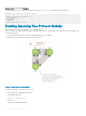
For example, as shown in the following illustration (STP topology 1, upper left) Switch A is the root bridge in the network core. Switch C
functions as an access switch connected to an external device. The link between Switch C and Switch B is in a Blocking state. The ow of
STP BPDUs is shown in the illustration.
In STP topology 2 (shown in the upper right), STP is enabled on device D on which a software bridge application is started to connect to
the network. Because the priority of the bridge in device D is lower than the root bridge in Switch A, device D is elected as root, causing
the link between Switches A and B to enter a Blocking state. Network trac then begins to ow in the directions indicated by the BPDU
arrows in the topology. If the links between Switches C and A or Switches C and B cannot handle the increased trac ow, frames may be
dropped.
In STP topology 3 (shown in the lower middle), if you have enabled the root guard feature on the STP port on Switch C that connects to
device D, and device D sends a superior BPDU that would trigger the election of device D as the new root bridge, the BPDU is ignored and
the port on Switch C transitions from a forwarding to a root-inconsistent state (shown by the green X icon). As a result, Switch A becomes
the root bridge.
Figure 126. STP Root Guard Prevents Bridging Loops
Conguring Root Guard
Enable STP root guard on a per-port or per-port-channel basis.
Dell EMC Networking OS Behavior: The following conditions apply to a port enabled with STP root guard:
• Root guard is supported on any STP-enabled port or port-channel interface except when used as a stacking port.
• Root guard is supported on a port in any Spanning Tree mode:
Spanning Tree Protocol (STP)
949