S6100-ON Installation Guide January 2019
Notes, cautions, and warnings NOTE: A NOTE indicates important information that helps you make better use of your computer. CAUTION: A CAUTION indicates either potential damage to hardware or loss of data and tells you how to avoid the problem. WARNING: A WARNING indicates a potential for property damage, personal injury, or death. © 2015 - 2019 Dell Inc. or its subsidiaries. All rights reserved. Dell, EMC, and other trademarks are trademarks of Dell Inc. or its subsidiaries.
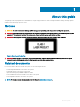
Contents 1 About this guide............................................................................................................................................. 5 Notices................................................................................................................................................................................ 5 Related documents..........................................................................................................................................
System power-up..............................................................................................................................................................31 Power up sequence.................................................................................................................................................... 31 6 Power supplies.............................................................................................................................................
1 About this guide This guide provides site preparation recommendations, step-by-step procedures for rack mounting and desk mounting, inserting optional modules, and connecting to a power source. Notices CAUTION: To avoid electrostatic discharge (ESD) damage, wear grounding wrist straps when handling this equipment. WARNING: Only trained and qualified personnel can install this equipment. Read this guide before you install and power up this equipment. This equipment contains two power cords.
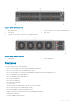
2 S6100–ON system The following sections describe the Dell S6100–ON system: Topics: • Introduction • Features • Physical dimensions • Luggage tag • System status • LED display • Prerequisites • S6100–ON configurations Introduction S6100-ON is a two rack unit 10/25/40/100 GbE switch. A fully loaded system includes 64 quad form-factor pluggable (QSFP+ or QSFP28) optics for 40/100 GbE aggregation and 10/25/40/100 GbE top of rack (ToR) and end of row (EoR) applications.
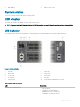
Figure 2. S6100–ON I/O-side view 1 MicroUSB-B port 2 64 x 10/40 QSFP+ or 32 x 10/25/40/100 QSFP28 3 USB Type A 4 SFP+ ports 5 Top: RJ-45 console port. Bottom: RJ-45 management port 2 Power supply units Figure 3.
• Real time clock (RTC) support • Hot-pluggable redundant power supplies • Power management monitoring • Four hot-pluggable replaceable fan modules • Standard 2U chassis • Two-hole ground lug Physical dimensions The S6100-ON has the following physical dimensions: • 442 x 510 x 86.75 mm (W x D x H) • 17.40 x 20 x 3.41 inches (W x D x H) Luggage tag The S6100–ON system has a pull-out tag, known as a luggage tag, on the I/O-side of the system. Figure 4.
3 MAC address 4 Express service code System status You can view S6100–ON status information using the LEDs. LED display The S6100–ON includes LED displays on the I/O side of the system. NOTE: If you are installing third-party software, for LED information, see your third-party operating software documentation. LED behavior The following S6100–ON system LED behavior is seen during open networking installation environment (ONIE) operations: Figure 5.
LED Description • Blinking amber—Minor system error Power LED • • • • Off—No power Solid green—Normal Operation Solid amber—POST is in process Blinking amber—Noncritical system error—power supply failure Master LED • • Off—Switch is in Stacking Slave mode Solid green—System is in Stacking Master or Standalone mode Management LED • • • • Off—No Link Solid green—Link on 1 Gbps speed Solid amber—Link on 10/100 Mbps speeds Blinking green—Port activity FAN LED • • • Off—No power Solid green—fan pow
LED Description • Flashing amber, ~30 ms—Port link is 4x10 GbE Table 4. QSFP28 Port LEDs—2x40GbE Mode LED Description Link LED • • Off—No Link Solid green—Port link is 2x40 GbE Activity LED • • Off—No Link Flashing amber, ~30 ms—Port link is 2x40 GbE Table 5.
S6100–ON configurations You can order the S6100–ON system in several different configurations. • S6100–ON AC or DC Normal Airflow: thirty–two 10/25/40/100 GbE ports with four SFP+ 10 GbE ports, two AC or DC power supply units and four fan subsystems. Fan airflow is from the I/O side to the power supply side. • S6100–ON AC or DC Reverse Airflow: thirty–two 10/25/40/100 GbE ports with four SFP+ 10 GbE ports, two AC or DC power supply units and four fan subsystems.
3 Site preparations The S6100–ON is suitable for installation as part of a common bond network (CBN). You can install the system in: • Network telecommunication facilities • Data centers • Other locations where the National Electric Code (NEC) applies For more information about S6100–ON specifications, see Specifications. NOTE: Install the S6100–ON system into a rack before installing any optional components.
Rack mounting When you prepare your equipment rack, ensure that the rack is grounded. Ground the equipment rack to the same ground point the power service in your area uses. The ground path must be permanent. System ground Dell recommends grounding your system. Use the S6100–ON in a common bond network (CBN). Connect the grounding cables as described in S6100-ON installation. Fans and airflow The S6100–ON fans support two airflow options: normal and reverse.
• Store on a dry surface or floor, away from direct sunlight, heat, and air conditioning ducts. • Store in a dust-free environment. NOTE: ESD damage can occur when components are mishandled. Always wear an ESD-preventive wrist or heel ground strap when handling the S6100–ON and its accessories. After you remove the original packaging, place the S6100–ON and its components on an anti-static surface.
4 NEBS compliance For your system to be network equipment building system (NEBS) compliant, you must follow the instructions detailed in this chapter. To be NEBS-compliant, orient your system in the rack so that the air inlet is from the front aisle and the air exhaust is to the rear aisle.
For rack spans from 22 to 23.375 inches The switch ships without the ground lug attached. To be NEBS-compliant, attach the ground lug using these steps. Figure 6. Switch without ground lug 1 Remove the ground lug from the shipping bag and crimp the ground wire to the lug. The ground wire is not included. NOTE: The grounding cable must comply with your local electrical codes in size and color. Wires are typically green or green with a yellow stripe.
Rack rail screws are not included. Figure 8. Attach rack rails to rack—front view Figure 9. Rack rails installed 4 Insert the chassis into the rack from the front. Secure the chassis with captive screws and two additional rack screws on each side of the front of the rack. Rack rail screws are not included.
Figure 10. Secure chassis in rack 5 Attach the other end of the ground wire to the nearest appropriate facility grounding post. For rack spans from 23.375 to 36 inches The switch ships without the ground lug attached. To be NEBS-compliant, attach the ground lug using these steps. Figure 11. Switch without ground lug 1 Remove the ground lug from the shipping bag and crimp the ground wire to the lug. The ground wire is not included.
Figure 12. Switch with ground lug NOTE: For proper ventilation, position the chassis in an equipment rack or cabinet with a minimum of 5 inches (12.7 cm) of clearance around exhaust vents. The acceptable ambient temperature ranges are listed in the Environmental Parameters section. 3 Attach the rack rails to the rack using four screws on the front of the rack and eight screws on the back of the rack. Rack rail screws are not included. Figure 13.
Figure 14. Attach rack rails to rack—front view Figure 15. Rack rails installed 4 Insert the chassis into the rack from the front. Secure the chassis with captive screws and two additional rack screws on each side of the front of the rack. Rack rail screws are not included.
Figure 16. Secure chassis in rack 5 Attach the other end of the ground wire to the nearest appropriate facility grounding post.
5 S6100–ON installation To install the S6100–ON system, Dell recommends completing the installation procedures in the order presented. Topics: • • • • • • • • • • Installation overview Unpack the S6100-ON System Four-post rack assembly Four-post rack mount Chassis ground I/O module installation SFP+ and QSFP optics installation SFP+ and QSFP optics removal Port connectivity System power-up Installation overview Always handle the S6100–ON and its components with care.
• One S6100-ON switch • One RJ-45 to DB-9 female cable • Two sets of rail kits, no tools required • Two PSUs • Four fan units • One AC or DC country and region-specific power cord • One ground lug • Dell Networking Getting Started Guide for the S6100–Open Networking (ON) System • Safety and Regulatory Information • Warranty and Support Information Unpack the system by carefully removing the device from the container and placing it on a secure and clean surface.
NOTE: The illustrations in this document are not intended to represent a specific switch. System install and remove 1 Align the system with rails and slide the system into rack. 2 Tighten the screws on each side of the systems’s front panel, item 1. To remove the system from the rack, loosen the screws and slide the system out of the rack. Figure 17.
NOTE: Coat the two-hole lug with an anti-oxidant compound before crimping. Also, bring any unplated mating surfaces to a shiny finish and coat with an anti-oxidant before mating. Plated mating surfaces must be clean and free from contamination. NOTE: Never use the same bolts to secure multiple grounding cables. 1 Locate the chassis ground lug nuts and holes on the chassis back. Figure 18.
Figure 19. Cable connector 1 High-strand-count conductor 2 Two-holes for cable—.27 ±.02 DIA I/O module installation NOTE: Install a blank panel in any unused switch I/O slot. NOTE: The S6100-ON has capacitors on the front-left corner of the PC board. To avoid damaging these capacitors, align the I/O module with the yellow arrows located inside the chassis and then gently slide the I/O module in place. 1 Remove the I/O module from the electro-static bag.
Figure 20. I/O module installation 1 Ejector lever 3 I/O module 2 Orange release tab Important points The S6100–ON is designed to support two hot-swappable power supplies with integrated fans that provide cooling for the chassis. • The S6100–ON ships with two power supplies. • The PSU slides into the slot smoothly. Do not force the PSU into a slot as this action may damage the PSU or the S6100-ON chassis.
NOTE: The Utility panel consists of two slots, PSU1 and PSU2. Insert PSUs in both slots. NOTE: If you remove and re-insert a module in the same slot, the system detects the module. However, if you remove a module from a slot and insert a different module into that same slot, the system does not detect the new module. SFP+ and QSFP optics installation The S6100–ON has SFP+, QSFP+, and QSFP28 optical ports. For a list of supported optics, contact your Dell representative.
Figure 21. 8 x 100G module port pipes Table 7. Port and port pipe distribution—16 x 40G modules Slot/Port Port pipe 1/13, 1/14, 1/15, 1/16, 2/1, 2/2. 2/3. 2/4, 3/1, 3/2, 3/3, 3/4, 4/5, 4/6, 4/7, 4/8 0—red 1/9, 1/10, 1/11, 1/12, 2/5, 2/6, 2/7, 2/8, 3/13, 3/14, 3/15, 3/16, 4/9, 4/10, 4/11, 4/12 1—orange 1/5, 1/6, 1/7, 1/8, 2/9, 2/10, 2/11, 2/12, 3/9, 3/10, 3/11, 3/12, 4/13, 4/14, 4/15, 4/16 2—green 1/1, 1/2, 1/3, 1/4, 2/13, 2/14, 2/15, 2/16, 3/5, 3/6, 3/7, 3/8, 4/1, 4/2, 4/3, 4/4 3—blue Figure 22.
Figure 23. 4 x CXP + 4 x QSFP28 port pipes System power-up Supply power to the S6100–ON after it is mounted in a rack or cabinet. Dell recommends reinspecting your system before powering up. Verify the following: • The equipment is properly secured to the rack and properly grounded—recommended. • The equipment rack is properly mounted and grounded—recommended.
6 Power supplies The S6100–ON supports AC or DC power supplies with two air-flow directions, normal and reverse. Normal airflow is from the I/O to the PSU and reverse airflow is from the PSU to the I/O. Two PSUs are required for full redundancy, but the system can operate with a single PSU. To protect against high-voltage shock, install a power supply blank in all unused power supply slots. The PSU is field replaceable.
The PSUs have an integrated fan, which you cannot replace individually; if the fan integrated in a PSU fails, you must replace the entire PSU. You can replace the fan trays individually. For fan tray replacement procedures, see Fans. WARNING: Prevent exposure and contact with hazardous voltages. Do not attempt to operate this system with the safety cover removed. CAUTION: Remove the power cable from the PSU before removing the PSU.
4 Plug in the appropriate AC three prongs power cord from the switch PSU to the external power source. 5 Repeat steps 1 through 4 above using the second PSU slot on the S6100-ON system. NOTE: The S6100-ON powers up when the cables are connected between the power supply and the power source. DC power supply connection Each DC powered system comes with a set containing a prewired, 3-inch 8 AWG, power supply connector and a four-screw wiring block. One set is provided for each DC PSU. Figure 26.
Figure 27. DC power connector ground 1 Ground nut 2 Washer 3 Lock washer 4 Ground cable 5 Device grounding rod 1 Strip 1/2 inches of insulation from each of the power connector’s red and black wires, as shown. 2 Insert each of the power connector’s bare wire lengths into the wiring block. Insert red into one hole and black into the other hole, as shown. 3 Use a flat-blade screwdriver to tighten the screws that secures the bare wires into the wiring block.
7 Fans The S6100–ON comes from the factory with two PSUs and four fan module installed in the chassis. The fan module and power supply, which have integrated fans, are hot-swappable. In addition to the power supply modules, you can order and install fan modules separately. The S6100-ON supports two airflow direction options. DO NOT mix airflow types in a chassis; you can use only a single airflow direction in a chassis. If the airflow directions are mismatched, the S6100-ON issues an alarm.
1 Fan modules Fan module installation The fan module in the S6100–ON is field replaceable. Module slot 1 is on the left side of the chassis and module slot 4 is on the right side of the chassis. CAUTION: DO NOT mix airflow directions. All fans must use the same airflow direction—reverse or normal. If you mix the airflow direction, the switch detects the discrepancy, issues an alarm, and may auto-shutdown to avoid heat damage to components. You must correct the mixed airflow direction.
Fan air filter replacement Environmental factors can decrease the amount of time required between air filter replacements. Check the environmental factors regularly. An increase in temperature and/or particulate matter in the air might affect performance. CAUTION: Check the fan air filters at six-month intervals and replace them as necessary. To accurately determine air filter replacement intervals, regularly monitor the speeds of the cooling fans.
8 Management ports Besides the 10/25/40/50/100 GbE RJ-45 ports, the S6100–ON system provides several ports for management and storage. Topics: • RS-232 console port access • Micro USB-B console port access • USB storage • Before you install an OS • ONIE service discovery RS-232 console port access The RS-232 console port is on the I/O-side of the S6100-ON chassis, as shown. Figure 30.
Accessing the RJ-45 Console Port with a DB-9 Adapter You can connect to the console using an RJ-45 to RJ-45 rollover cable and an RJ-45 to DB-9 female DTE adapter to a terminal server (for example, a PC). The pin assignments between the console and a DTE terminal server are as follows: Table 9.
7 Confirm that the terminal settings on your terminal software emulation program are as follows: • 115200 baud rate • No parity • 8 data bits • 1 stop bit • No flow control USB storage The USB storage supports the FAT file system. The USB storage does not automatically mount. To use USB storage, first mount the device. 1 Create a mount directory for the USB. ONIE:/ # mkdir /mnt/usb 2 View the fixed disks using the fdisk command. ONIE:/mnt # fdisk -l For internal storage: Disk /dev/sda: 15.
To select an entry, use the up and down arrow keys. Press Enter to select an OS or enter e to edit the commands before booting. Enter c for a command line. The selected entry runs automatically in the operating system. NOTE: These output examples are for reference only; your output may be different. Grub bootloader example GNU GRUB version 2.
You can install an operating system manually from HTTP, FTP, or TFTP using the onie-nos-install command. The ONIE Install environment uses DHCP to assign an IP address to the management interface, eth0. If that fails, it uses the default IP address 192.168.3.10/255.255.255.0. NOTE: These output examples are for reference only; your output may be different. To display the IP address, use the ifconfig eth0 command, as shown.
9 Dell support The Dell Support site provides a range of documents and tools to help you effectively use the Dell equipment and the impact of network outages. You can obtain technical information regarding Dell products, access software upgrades and patches, download available management software, and manage your open cases. The Dell support site provides integrated, secure access to these services. To access the Dell Support site, go to www.dell.com/support/.
Figure 31.
10 Specifications This topic lists the S6100–ON specifications. CAUTION: Operate the product at an ambient temperature not higher than 113°F (45°C). CAUTION: Lithium Battery Caution: There is a danger of explosion if the battery is incorrectly replaced. Replace only with same or equivalent type of battery. Dispose of the batteries according to the manufacturer's instructions. NOTE: For RoHS information, see Restricted Material Compliance.
Parameter Specifications Storage Humidity 5 to 95 percent, non-condensing Thermal Output Typical: 1170.4 BTU/hr (343 W) Maximum: 3057.3 BTU/hr (896 W) Maximum operational altitude 10,000 feet (3,048 meters) Maximum non-operational altitude No performance degradation to 35,000 feet (10,668 meters) Shock SV0115 — ODM Table 12. AC power requirements Parameter Specifications Power Supply 100–240 VAC 50/60 Hz Maximum Current Draw Per System 12A–6.
• 802.3bm 100 Gigabit Ethernet Agency compliance The S6100–ON is designed to comply with the following safety and agency requirements. USA Federal Communications Commission (FCC) statement This equipment has been tested and found to comply with the limits for a Class A digital device, pursuant to Part 15 of the FCC rules. These limits are designated to provide reasonable protection against harmful interference when the equipment is operated in a commercial environment.
Germany http://www.force10networks.com/german/ Tel: +49 172 6802630 Email: EMEA Central Sales Japan: VCCI Compliance for Class A Equipment Figure 33. Japan: VCCI Compliance for Class A Equipment This is Class A product based on the standard of the Voluntary Control Council For Interference by Information Technology Equipment (VCCI). If this equipment is used in a domestic environment, radio disturbance may arise. When such trouble occurs, the user may be required to take corrective actions.
Figure 36. Korean Package Label Safety Standards and Compliance Agency Certifications • CUS UL 60950-1, 2nd Edition • CSA 60950-1-03, 2nd Edition • EN 60950-1, 2nd Edition • EN 60825-1, 1st Edition • EN 60825-1 Safety of Laser Products—Part 1: Equipment Classification Requirements and User’s Guide • EN 60825-2 Safety of Laser Products—Part 2: Safety of Optical Fibre Communication Systems • FDA Regulation 21CFR 1040.10 and 1040.
• EN 61000-3-2 Harmonic Current Emissions • EN 61000-3-3 Voltage Fluctuations and Flicker • EN 61000-4-2 ESD • EN 61000-4-3 Radiated Immunity • EN 61000-4-4 EFT • EN 61000-4-5 Surge • EN 61000-4-6 Low Frequency Conducted Immunity Product recycling and disposal You must recycle or discard this system according to applicable local and national regulations.