
Install Guide


LED Description
• Flashing amber, ~30 ms—Port link is 4x10 GbE
Table 4. QSFP28 Port LEDs—2x40GbE Mode
LED Description
Link LED
• O—No Link
• Solid green—Port link is 2x40 GbE
Activity LED
• O—No Link
• Flashing amber, ~30 ms—Port link is 2x40 GbE
Table 5. SFP+ port LEDs
LED Description
Link LED
• O—No Link
• Solid green—Port activity operating at maximum port speed
• Solid amber—Port activity operating at lower speed
Activity LED
• O—No Link
• Flashing green, ~30 ms—port activity operating at maximum
port speed
• Flashing amber, ~30 ms—port activity operating at lower port
speed
Prerequisites
The following is a list of components required for successful installation of the S6100-ON:
NOTE
: Detailed installation instructions for the S6100-ON are provided in Site preparations and S6100-ON Installation.
• S6100–ON chassis or multiple chassis, if stacking
• AC or DC country and regional-specic cables to connect the AC or DC power source to each of the chassis’ AC or DC power supplies
• Mounting brackets for rack installation, included
• Screws for rack installation
• #1 and #2 Phillips screw drivers, not included
• Torx screwdriver, not included
• Ground cable screws, included
• Copper or ber cables
Other optional components are:
• Ground cable
• Extra power supply unit
• Extra fan module
• Extra mounting brackets
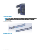
S6100–ON system
11