
Install Guide


NOTE: Coat the two-hole lug with an anti-oxidant compound before crimping. Also, bring any unplated mating surfaces to a
shiny nish and coat with an anti-oxidant before mating. Plated mating surfaces must be clean and free from contamination.
NOTE: Never use the same bolts to secure multiple grounding cables.
1 Locate the chassis ground lug nuts and holes on the chassis back.
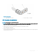
Figure 18. Chassis ground connector
1
Ground cable 2 Two-hole chassis ground connector
2 Install the grounding cables to the ground nuts.
The grounding cable must comply with your local electrical codes in size and color. Wires are typically green or green with a yellow
stripe.
NOTE
: For proper ventilation, position the chassis in an equipment rack or cabinet with a minimum of 5 inches (12.7 cm)
of clearance around exhaust vents. The acceptable ambient temperature ranges are listed in the Environmental
Parameters section.
3 Tighten the M5 screws, torque between 18 and 24 in-lbs.
4 Connect the opposite end of the grounding cable to the nearest appropriate facility grounding post.
26
S6100–ON installation