
Install Guide


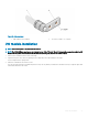


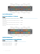

Figure 19. Cable connector
1 High-strand-count conductor 2 Two-holes for cable—.27 ±.02 DIA
I/O module installation
NOTE: Install a blank panel in any unused switch I/O slot.
NOTE: The S6100-ON has capacitors on the front-left corner of the PC board. To avoid damaging these capacitors, align the I/O
module with the yellow arrows located inside the chassis and then gently slide the I/O module in place.
1 Remove the I/O module from the electro-static bag.
2 Open the left ejector lever, item 1, by pressing in the orange tab, item 2, and rotating it to the right.
The level snaps into the open position.
3 Slide the I/O module into the switch I/O slot.
The slot is keyed so that the I/O module fully inserts in only one way. When you install the I/O module correctly, it snaps into place and
is ush with the back of the switch.
S6100–ON installation
27