Dell EMC PowerSwitch Z9100–ON Installation Guide March 2021 March 2021 Rev.
Notes, cautions, and warnings NOTE: A NOTE indicates important information that helps you make better use of your computer. CAUTION: A CAUTION indicates either potential damage to hardware or loss of data and tells you how to avoid the problem. WARNING: A WARNING indicates a potential for property damage, personal injury, or death. © 2015 - 2021 Dell Inc. or its subsidiaries. All rights reserved. Dell, EMC, and other trademarks are trademarks of Dell Inc. or its subsidiaries.
Contents Chapter 1: About this guide........................................................................................................... 5 Related documents............................................................................................................................................................. 5 Chapter 2: The Z9100–ON switch.................................................................................................. 6 Introduction..............................................
Chapter 6: Power supplies...........................................................................................................28 Components....................................................................................................................................................................... 28 AC or DC power supply installation...............................................................................................................................29 DC power supply connection......
1 About this guide This guide provides site preparation recommendations, step-by-step procedures for rack mounting and desk mounting, inserting optional modules, and connecting to a power source. CAUTION: To avoid electrostatic discharge (ESD) damage, wear grounding wrist straps when handling this equipment. NOTE: Only trained and qualified personnel can install this equipment. Read this guide before you install and power up this equipment. This equipment contains two power cords.
2 The Z9100–ON switch The following sections describe the Dell EMC Z9100–ON switch: Topics: • • • • • • • • Introduction Features Physical dimensions LED display Prerequisites Z9100–ON configurations Switch status Luggage tag Introduction The Z9100-ON is a one rack unit compact 10/25/40/50/100 GbE switch. The switch includes 32 fixed quad form-factor pluggable 28 (QSFP28) optics for 40/100 GbE aggregation and 10/25/40/50 GbE top-of-rack (ToR) and end-of-row (EoR) applications.
Figure 3. Z9100–ON PSU-side view 1. Fan modules 2. Power supply units Features The Z9100–ON offers the following features. ● ● ● ● ● ● ● ● ● ● ● ● ● QSFP ports support 10/25/40/50/100 GbE Two 1000M/10G SFP+ ports One micro universal serial bus (MicroUSB-B) console port One 2.0 USB Type-A port for additional file storage One 10/100/1000BaseT Ethernet management port Rangeley central processing unit (CPU) system with 8GB DDR III RAM.
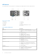
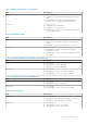
LED behavior The following Z9100–ON switch LED behavior is seen during open networking installation environment (ONIE) operations: Figure 4. Z9100–ON LEDs 1. 3. 5. 7. 9. Master LED Locator LED SFP+ LED SFP+ LED Fan LED 2. 4. 6. 8. 10. Switch LED QSFP28 LED Stack ID RJ45 Ethernet Management Port LEDs Power LED Table 1. Z9100–ON LED behavior LED Description Master LED ● Off—Switch is in Stacking Slave mode. ● Solid Green—Switch is in Stacking Master or Standalone mode.
Table 1. Z9100–ON LED behavior (continued) LED Description Fan LED ● Off—No powe.r ● Solid green—Fan powered and running at the expected RPM. ● Flashing amber—Fan failed or incompatible airflow direction, PSU or fan trays with differing airflows. Power LED ● ● ● ● Off—No power. Solid green—Normal operation. Solid amber—POST in progress. Blinking amber—Noncritical system error; PSU fan failure or power supply failure. Table 2. QSFP28 port LEDs LED Description Link LED ● Off—No link.
Prerequisites The following is a list of components needed for successful installation of the Z9100-ON: NOTE: Detailed installation instructions for the Z9100-ON are provided in Site Preparations and Install the Z9100-ON. ● Z9100–ON switch, or multiple switches if stacking ● AC or DC country- and regional-specific cables. Used to connect the AC or DC power source to each of the switches’ AC or DC power supplies.
Switch status You can view Z9100–ON status information using the light emitting diodes (LEDs). Luggage tag The Z9100–ON switch has a pull-out tag, known as a luggage tag, on the I/O-side of the switch. The luggage tag includes switch ID information. Figure 5. Z9100–ON luggage tag 1. Service tag 3. MAC address 2. PPID 4.
3 Site preparations The Z9100–ON is suitable for installation as part of a common bond network (CBN). You can install the switch in: ● Network telecommunication facilities ● Data centers ● Other locations where the National Electric Code (NEC) applies For more information about Z9100–ON specifications, see Specifications. NOTE: Install the Z9100–ON switch into a rack or cabinet before installing the components.
Rack mounting When you prepare your equipment rack, ensure that the rack is grounded. Ground the equipment rack to the same ground point the power service in your area uses. The ground path must be permanent. Z9100–ON ground Dell EMC recommends you ground the Z9100-ON switch. Use your switch in a common bond network (CBN). Connect the grounding cables as described in Z9100-ON Installation. Fans and airflow The Z9100–ON fans support two airflow options: normal and reverse.
NOTE: ESD damage can occur when components are mishandled. Always wear an ESD-preventive wrist or heel ground strap when handling the Z9100–ON and its accessories. After you remove the original packaging, place the Z9100–ON and its components on an antistatic surface.
4 NEBS compliance For your switch to be network equipment building system (NEBS) compliant, you must follow the instructions detailed in this section. To be NEBS compliant, orient your switch in the rack so that the air inlet is from the front aisle and the air exhaust is to the back aisle.
Figure 6. GND lug assembly 1. Remove the two installed M3 screws from the lower-left side of your switch. NOTE: Keep these screws. 2. Remove the bracket assembly from the shipping bag. 3. Clean the bracket and lug surfaces thoroughly, and apply an anti-oxidant solution to the mating surfaces. 4. Attach the switch ground using the Ground cable instructions. 5. Using the two removed screws, attach the GND lug bracket assembly to your switch, as shown. Torque the M3 screws to ±4–5 in-lbs. Figure 7.
Figure 8. GND lug assembly attached 6. Install your switch into your rack using the Z9100-ON Installation instructions.
5 Z9100–ON installation To install the Z9100–ON switch, complete the installation procedures in the order described. Always handle the Z9100–ON and its components with care. Avoid dropping the switch or its field replaceable units (FRUs). NOTE: ESD damage can occur if components are mishandled. Always wear an ESD-preventive wrist or heel ground strap when handling the Z9100–ON and its components.
In both configurations, the ground cable is not included. To properly ground the switch, Dell EMC recommends a one- or two-hole lug, M3 or M4 hole size. The switch hole lugs must be a UL-recognized, crimp-type lug. CAUTION: Grounding conductors must be made of copper. Do not use aluminum conductors. NOTE: Coat the one-hole lug with an anti-oxidant compound before crimping. Also, bring any unplated mating surfaces to a bright finish and coat with an anti-oxidant before mating.
ReadyRails installation The ReadyRails rack mounting system is provided to easily configure your rack for installation of your Z9100–ON switch. You can install the ReadyRails system using the 1U tool-less method or one of three possible 1U tooled methods. The tooled installation methods include two-post flush mount, two-post center mount, or four-post threaded. CAUTION: Do not use this method if you need your switch to be NEBS Earthquake Z4-compliant. 1. Face the ReadyRails flange ears facing outward.
Figure 10. Two-post flush-mount configuration 2. Attach one rail to the front post flange with two user-supplied screws, item 2. 3. Slide the plunger bracket forward against the vertical post and secure the plunger bracket to the post flange with two user-supplied screws, item 3. 4. Repeat this procedure for the second rail. Two-post center-mount configuration CAUTION: Your switch is not NEBS Earthquake Z4-compliant if you use this installation method. 1.
Figure 11. Two-post center-mount configuration 2. Slide the back bracket towards the post. Secure it to the post flange with two user-supplied screws, item 2. 3. Repeat this procedure for the second rail. Four-post threaded configuration CAUTION: To be NEBS Earthquake Z4-compliant, you must remove the tool-less latch castings described in Step 1. 1. Remove the latch castings from each end of the ReadyRails assemblies. To remove the two screws each latch casting, use a Torx driver, item 1.
Figure 12. Four-post threaded configuration 2. For each rail, attach the front and back flanges to the post flanges with two user-supplied screws at each end, item 2. Z9100-ON switch installation You can mount the switch in the 1U front-rack or 1U two-post flush and center configurations. The following is an example of a front-rack configuration. For the 1U two-post flush and center configurations, slide the switch into the rails in the same manner as the four-post configurations.
Figure 13. Switch rail attachment 2. After you install both rails, line them up on the ReadyRails. Slide the switch in until it is flush with front of rack. About three inches before you fully insert your switch, the rail locking feature engages to keep the switch from inadvertently sliding out and falling. Figure 14. Front rack installation NOTE: Do not the use the mounted ReadyRails as a shelf or a workplace.
Optics installation The Z9100–ON has two SFP+ optical ports. For a list of supported optics, see the Z9100–ON specification sheet at www.dell.com/support or contact your Dell EMC sales representative. WARNING: When working with optical fibers, follow all warning labels and always wear eye protection. Never look directly into the end of a terminated or unterminated fiber or connector as this action can cause eye damage. NOTE: ESD damage can occur if components are mishandled.
Figure 15. Port pipes Switch power up Supply power to the Z9100–ON after it is mounted in a rack or cabinet. Dell EMC recommends re-inspecting your switch before powering it up. Verify the following: ● The equipment is properly secured to the rack and properly grounded, recommended. ● The equipment rack is properly mounted and grounded, recommended. ● The ambient temperature around the unit, which may be higher than the room temperature, is within the limits specified for the Z9100–ON.
If you are using the fan trays or PSUs in the replacement switch, remove them from the switch. 5. Unpack the new switch. For more information, see Unpack. 6. Confirm that the software version of the replacement switch is the same as the previously installed switch. show os-version If the software versions do not match, upgrade the replacement switch software using the procedure included with the firmware download. 7. Copy the backed-up switch configuration to the new switch.
6 Power supplies The switch ships with two AC or DC power supplies. The power supplies have two air-flow directions, normal and reverse. Normal is from the I/O-side to the PSU-side. Reverse is from the PSU-side to the I/O-side. Two PSUs are required for full redundancy, but the switch can operate with a single PSU. The PSUs are field replaceable. When running with full redundancy—two power supplies installed and running, you can remove and replace one PSU without disrupting traffic.
WARNING: Prevent exposure and contact with hazardous voltages. Do not attempt to operate this switch with the safety cover removed. CAUTION: Remove the power cable from the PSU before removing the PSU. Also, do not connect the power cable before you insert the PSU in the switch. NOTE: To comply with the GR-1089 Lightning Criteria for Equipment Interfacing with AC or DC Power Ports, use an external surge protection device (SPD) at the AC or DC input of the router.
Figure 18. DC power connector and wiring block 1. 3. 5. 7. DC wire RTN Captive screws (2) PSU status LED DC wire –48V 2. DC power connector 4. Orange tab 6. DC power socket Figure 19. DC power connector ground 1. Ground nut 3. Lock washer 5. Device grounding rod 2. Washer 4. Ground cable To connect a DC PSU to the site’s DC power source, follow these steps: 1. Strip 1/2 inches of insulation from each of the power connector’s wires (RTN and –48V), as shown. 2.
NOTE: Do not cross the wires—In the wiring block, RTN aligns with RTN and –48V aligns with –48V. 5. Insert the DC power connector into the power socket of the DC PSU. Ensure that the connector pins firmly seat and you hear the click of the power connector’s left and right levered clamps lock into place. NOTE: Never try to force the power connector into or out of the DC PSU power socket. NOTE: To remove the power connector from a DC PSU, use the orange tab on the side of the connector.
7 Fans The Z9100–ON comes from the factory with two PSUs and five fan modules installed in the switch. The fan modules and PSUs, which have integrated fans, are hot-swappable. In addition to the power supply modules, you can order and install fan modules separately. The Z9100-ON requires a minimum of four running fans. The Z9100-ON supports two airflow direction options. Do not mix airflow types in a switch; you can use only a single airflow direction in a switch.
Fan module installation The fan modules are field replaceable. Module slot 1 is on the left side of the switch; module slot 5 is on the right side of the switch. CAUTION: DO NOT mix airflow directions. All reverse or normal fans must use the same airflow direction. If you mix the airflow direction, the switch detects the discrepancy, issues an alarm, and may autoshutdown to avoid heat damage to the components. If an autoshutdown occurs, correct the mixed airflow direction. 1.
3. Slide the existing filter upwards to remove it from the module. 4. Replace the filter with a new filter of the same size. 5. Repeat for the remaining modules that need the filter replaced.
8 Management ports The Z9100–ON switch provides several ports for management and storage. Topics: • • • • • RS-232 console port access MicroUSB-B console port access USB storage Before you install an OS Switch check RS-232 console port access The RS-232 console port is on the I/O-side of the Z9100-ON switch. Figure 22. Z9100–ON RS-232 console ports 1.
MicroUSB-B console port access The MicroUSB type B console port is on the I/O side of the switch. NOTE: The Z9100-ON switch uses the Silicon Labs CP2102 USB-B chip. To find the correct USB-B universal asynchronous receiver-transmitter (UART) driver, see https://www.silabs.com/products/development-tools/software/ usb-to-uart-bridge-vcp-drivers. When you connect the MicroUSB-B port, it becomes the primary connection and, while connected, all messages are sent to the microUSB-B port. 1. Power on the PC. 2.
4. Add a device to the file systems table (fstab) and mount the file systems—recommended. ONIE:/ # vi /etc/fstab # FSTAB entry for the ONIE-BOOT partition mounted on /boot LABEL=ONIE-BOOT /mnt/onie-boot ext4 defaults,rw,errors=remount-ro 0 /dev/sdb /mnt/usb vfat defaults 0 1 1 ONIE:/ # mount -a Before you install an OS After powering on the Z9100-ON switch, it goes through a power-on self-test (POST).
Switch check To confirm that ONIE is working properly, use the onie-sysinfo command. Run the onie-sysinfo command at the ONIE prompt. ONIE:/ # onie-sysinfo x86_64-dell_z9100_c2538-r0 ONIE:/ # onie-sysinfo –c (Machine arch) x86_64 ONIE:/ # onie-sysinfo –v (ONIE Version programmed) 3.23.1.0 ONIE:/ # ONIE:/ # uname -a Linux onie 3.2.35-onie+ #1 SMP Tue Dec 9 17:08:16 PST 2014 x86_64 GNU/Linux ONIE:/ # ONIE:/ # lspci 00:00.0 Class 0600: 8086:1f0c 00:01.0 Class 0604: 8086:1f10 00:02.
9 Specifications This topic lists the Z9100–ON specifications. CAUTION: Operate the product at an ambient temperature not higher than 113°F (45°C). CAUTION: Lithium Battery Caution: There is a danger of explosion if the battery is incorrectly replaced. Replace only with same or equivalent type of battery. Dispose of the batteries according to the manufacturer's instructions. NOTE: For RoHS information, see Restricted Material Compliance.
Table 8. Environmental parameters (continued) Parameter Specifications Storage temperature –40° to 158°F (–40° to 70°C) Storage humidity 5 percent to 90 percent, non-condensing Maximum thermal output 292.42 BTU/hr 85.7 W Maximum operational altitude 10,000 feet (3,048 meters) Maximum non-operational altitude 39,370 feet (12,000 meters) Shock SV0115 — ODM Table 9.
used in accordance to the instructions, it may cause harmful interference to radio communications. Operation of this equipment in a residential area is likely to cause harmful interference, in which case users will be required to take whatever measures necessary to correct the interference at their own expense. Properly shielded and grounded cables and connectors must be used in order to meet FCC emission limits.
Japan VCCI Compliance for Class A Equipment Figure 24. Japan VCCI Compliance for Class A Equipment This is Class A product based on the standard of the Voluntary Control Council For Interference by Information Technology Equipment (VCCI). If this equipment is used in a domestic environment, radio disturbance may arise. When such trouble occurs, the user may be required to take corrective actions. NOTE: Use the AC power cords with Dell EMC equipment only.
Figure 27. Korean package label Safety Standards and Compliance Agency certifications ● IEC 62368-1, 2nd Edition ● CUS UL 60950-1, 2nd Edition ○ Meets or exceeds Hi Pot and Ground Continuity testing per UL 60950-1.
● ● ● ● ● ● EN EN EN EN EN EN 61000-3-3 Voltage Fluctuations and Flicker 61000-4-2 ESD 61000-4-3 Radiated Immunity 61000-4-4 EFT 61000-4-5 Surge 61000-4-6 Low Frequency Conducted Immunity Product recycling and disposal You must recycle or discard this switch according to applicable local and national regulations. Dell EMC encourages owners of information technology (IT) equipment to responsibly recycle their equipment when it is no longer needed.
10 Dell EMC support The Dell EMC support site provides documents and tools to help you effectively use Dell EMC equipment and mitigate network outages. Through the support site you can obtain technical information, access software upgrades and patches, download available management software, and manage your open cases. The Dell EMC support site provides integrated, secure access to these services. To access the Dell EMC support site, go to www.dell.com/support.