Z9100–ON Installation Guide January 2019
Notes, cautions, and warnings NOTE: A NOTE indicates important information that helps you make better use of your computer. CAUTION: A CAUTION indicates either potential damage to hardware or loss of data and tells you how to avoid the problem. WARNING: A WARNING indicates a potential for property damage, personal injury, or death. © 2015 - 2019 Dell Inc. or its subsidiaries. All rights reserved. Dell, EMC, and other trademarks are trademarks of Dell Inc. or its subsidiaries.
Contents 1 About this guide............................................................................................................................................. 5 Regulatory........................................................................................................................................................................... 5 Related documents............................................................................................................................................
Port connectivity..............................................................................................................................................................25 Switch power up.............................................................................................................................................................. 26 After Z9100–ON installation..................................................................................................................................
1 About this guide This guide provides site preparation recommendations, step-by-step procedures for rack mounting and desk mounting, inserting optional modules, and connecting to a power source. CAUTION: To avoid electrostatic discharge (ESD) damage, wear grounding wrist straps when handling this equipment. WARNING: Only trained and qualified personnel can install this equipment. Read this guide before you install and power up this equipment. This equipment contains two power cords.
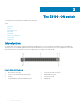
2 The Z9100–ON switch The following sections describe the Dell EMC Z9100–ON switch: Topics: • Introduction • Features • Physical dimensions • LED display • Prerequisites • Z9100–ON configurations • Switch status • Luggage tag Introduction The Z9100-ON is a one rack unit compact 10/25/40/50/100 GbE switch. The switch includes 32 fixed quad form-factor pluggable 28 (QSFP28) optics for 40/100 GbE aggregation and 10/25/40/50 GbE top-of-rack (ToR) and end-of-row (EoR) applications.
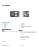
Figure 3. Z9100–ON PSU-side view 1 Fan modules 2 Power supply units Features The Z9100–ON offers the following features. • QSFP ports support 10/25/40/50/100 GbE • Two 1000M/10G SFP+ ports • One micro universal serial bus (MicroUSB-B) console port • One 2.0 USB Type-A port for additional file storage • One 10/100/1000BaseT Ethernet management port • Rangeley central processing unit (CPU) system with 8GB DDR III RAM.
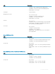
LED behavior The following Z9100–ON switch LED behavior is seen during open networking installation environment (ONIE) operations: Figure 4. Z9100–ON LEDs 1 Master LED 2 Switch LED 3 Locator LED 4 QSFP28 LED 5 SFP+ LED 6 Stack ID 7 SFP+ LED 8 RJ45 Ethernet Management Port LEDs 9 Fan LED 10 Power LED Table 1. Z9100–ON LED behavior LED Description Master LED • • Off—Switch is in Stacking Slave mode. Solid Green—Switch is in Stacking Master or Standalone mode.
LED Description • • • Solid green—Link on maximum speed, 1 Gbps speed. Solid amber—Link on lower speed, 10/100 Mbps speeds. Flashing green—Port activity. Stacking ID • Stack unit number. Management Port LED • • • • Off—No link or activity. Solid green—Port link on maximum speed. Solid amber—Port link on lower speed. Flashing green—Port activity. Fan LED • • • Off—No powe.r Solid green—Fan powered and running at the expected RPM.
Table 4. QSFP28 port LEDs for 2x50 GbE mode LED Description Link LED • • Off—No link. Solid green—Port link is 2x50 GbE. Activity LED • • Off—No link Flashing amber, ~30 ms—Port link is 2x50 GbE. Table 5. SFP+ port LEDs LED Description Link LED • • • Off—No link. Solid green—Link operating at maximum port speed. Solid amber—Link operating at lower speed. Activity LED • • • Off—No link. Flashing green, ~30 ms—port activity. Flashing amber, ~30 ms—port activity.
• Fan with airflow from the PSU side to the I/O side—reverse airflow • AC or DC power supply with airflow from the I/O side to the PSU side—normal airflow • AC or DC power supply with airflow from the PSU side to the I/O side—reverse airflow Switch status You can view Z9100–ON status information using the light emitting diodes (LEDs). Luggage tag The Z9100–ON switch has a pull-out tag, known as a luggage tag, on the I/O-side of the switch. The luggage tag includes switch ID information. Figure 5.
3 Site preparations The Z9100–ON is suitable for installation as part of a common bond network (CBN). You can install the switch in: • Network telecommunication facilities • Data centers • Other locations where the National Electric Code (NEC) applies For more information about Z9100–ON specifications, see Specifications. NOTE: Install the Z9100–ON switch into a rack or cabinet before installing the components.
The cabinet must meet minimum size requirements. Airflow must be in accordance with the Electronic Industries Alliance (EIA) standard. Ensure that there is a minimum of 5 inches (12.7 cm) between the intake and exhaust vents and the cabinet wall. Rack mounting When you prepare your equipment rack, ensure that the rack is grounded. Ground the equipment rack to the same ground point the power service in your area uses. The ground path must be permanent.
• Store on a dry surface or floor, away from direct sunlight, heat, and air conditioning ducts. • Store in a dust-free environment. NOTE: ESD damage can occur when components are mishandled. Always wear an ESD-preventive wrist or heel ground strap when handling the Z9100–ON and its accessories. After you remove the original packaging, place the Z9100–ON and its components on an antistatic surface.
4 NEBS compliance For your switch to be network equipment building system (NEBS) compliant, you must follow the instructions detailed in this section. To be NEBS compliant, orient your switch in the rack so that the air inlet is from the front aisle and the air exhaust is to the back aisle.
Figure 6. GND lug assembly 1 Remove the two installed M3 screws from the lower-left side of your switch. NOTE: Keep these screws. 2 Remove the bracket assembly from the shipping bag. 3 Clean the bracket and lug surfaces thoroughly, and apply an anti-oxidant solution to the mating surfaces. 4 Attach the switch ground using the Ground cable instructions. 5 Using the two removed screws, attach the GND lug bracket assembly to your switch, as shown. Torque the M3 screws to ±4–5 in-lbs. Figure 7.
Figure 8. GND lug assembly attached 6 Install your switch into your rack using the Z9100-ON Installation instructions.
5 Z9100–ON installation To install the Z9100–ON switch, complete the installation procedures in the order described. Always handle the Z9100–ON and its components with care. Avoid dropping the switch or its field replaceable units (FRUs). NOTE: ESD damage can occur if components are mishandled. Always wear an ESD-preventive wrist or heel ground strap when handling the Z9100–ON and its components.
Depending on the type of switch, to attach a ground cable to the switch, you need one of the included M3 or M4 screws. The switch ships with one of the following two configurations: • One threaded hole using an included M3 screw. • Two threaded holes using one of the two included M4 screws. In both configurations, the ground cable is not included. To properly ground the switch, Dell EMC recommends a one- or two-hole lug, M3 or M4 hole size. The switch hole lugs must be a UL-recognized, crimp-type lug.
• Reliable earthing—Maintain reliable earthing of rack-mounted equipment. Pay particular attention to the supply connections other than the direct connections to the branch circuit, for example: use of power strips. • Do not mount the equipment with the back panel facing downward. ReadyRails installation The ReadyRails rack mounting system is provided to easily configure your rack for installation of your Z9100–ON switch.
Figure 10. Two-post flush-mount configuration 2 Attach one rail to the front post flange with two user-supplied screws, item 2. 3 Slide the plunger bracket forward against the vertical post and secure the plunger bracket to the post flange with two user-supplied screws, item 3. 4 Repeat this procedure for the second rail. Two-post center-mount configuration CAUTION: Your switch is not NEBS Earthquake Z4-compliant if you use this installation method.
Figure 11. Two-post center-mount configuration 2 Slide the back bracket towards the post. Secure it to the post flange with two user-supplied screws, item 2. 3 Repeat this procedure for the second rail. Four-post threaded configuration CAUTION: To be NEBS Earthquake Z4-compliant, you must remove the tool-less latch castings described in Step 1. 1 Remove the latch castings from each end of the ReadyRails assemblies. To remove the two screws each latch casting, use a Torx driver, item 1.
Figure 12. Four-post threaded configuration 2 For each rail, attach the front and back flanges to the post flanges with two user-supplied screws at each end, item 2. Z9100-ON switch installation You can mount the switch in the 1U front-rack or 1U two-post flush and center configurations. The following is an example of a front-rack configuration. For the 1U two-post flush and center configurations, slide the switch into the rails in the same manner as the four-post configurations.
Figure 13. Switch rail attachment 2 After you install both rails, line them up on the ReadyRails. Slide the switch in until it is flush with front of rack. About three inches before you fully insert your switch, the rail locking feature engages to keep the switch from inadvertently sliding out and falling. Figure 14. Front rack installation NOTE: Do not the use the mounted ReadyRails as a shelf or a workplace.
Optics installation The Z9100–ON has two SFP+ optical ports. For a list of supported optics, see the Z9100–ON specification sheet at www.dell.com/support or contact your Dell EMC sales representative. WARNING: When working with optical fibers, follow all warning labels and always wear eye protection. Never look directly into the end of a terminated or unterminated fiber or connector as this action can cause eye damage. NOTE: ESD damage can occur if components are mishandled.
Figure 15. Port pipes Switch power up Supply power to the Z9100–ON after it is mounted in a rack or cabinet. Dell EMC recommends re-inspecting your switch before powering it up. Verify the following: • The equipment is properly secured to the rack and properly grounded, recommended. • The equipment rack is properly mounted and grounded, recommended. • The ambient temperature around the unit, which may be higher than the room temperature, is within the limits specified for the Z9100– ON.
4 Remove the switch from the rack. At the same time, press in the two side-release bars on the switch and slide the switch forward. If you are using the fan trays or PSUs in the replacement switch, remove them from the switch. 5 Unpack the new switch. For more information, see Unpack. 6 Confirm that the software version of the replacement switch is the same as the previously installed switch.
6 Power supplies The switch ships with two AC or DC power supplies. The power supplies have two air-flow directions, normal and reverse. Normal is from the I/O-side to the PSU-side. Reverse is from the PSU-side to the I/O-side. Two PSUs are required for full redundancy, but the switch can operate with a single PSU. The PSUs are field replaceable. When running with full redundancy—two power supplies installed and running, you can remove and replace one PSU without disrupting traffic.
1 PSU 1 and 2 The PSUs have an integrated fan, which you cannot replace individually; if the fan integrated in a PSU fails, you must replace the entire PSU. You can replace the fan trays individually. For fan tray replacement procedures, see Fans. WARNING: Prevent exposure and contact with hazardous voltages. Do not attempt to operate this switch with the safety cover removed. CAUTION: Remove the power cable from the PSU before removing the PSU.
DC power supply connection Each DC powered switch comes with a set containing a prewired (3-inch 8 AWG) power supply connector and a four-screw wiring block. One set is provided for each DC PSU. Figure 18. DC power connector and wiring block 1 DC wire RTN 2 DC power connector 3 Captive screws (2) 4 Orange tab 5 PSU status LED 6 DC power socket 7 DC wire –48V 2 Washer Figure 19.
3 Lock washer 5 Device grounding rod 4 Ground cable To connect a DC PSU to the site’s DC power source, follow these steps: 1 Strip 1/2 inches of insulation from each of the power connector’s wires (RTN and –48V), as shown. 2 Insert each of the power connector’s bare wire lengths into the wiring block. Insert RTN into one hole and –48V into the other hole, as shown. 3 Use a flat-blade screwdriver to tighten the screws that secures the bare wires into the wiring block.
7 Fans The Z9100–ON comes from the factory with two PSUs and five fan modules installed in the switch. The fan modules and PSUs, which have integrated fans, are hot-swappable. In addition to the power supply modules, you can order and install fan modules separately. The Z9100-ON requires a minimum of four running fans. The Z9100-ON supports two airflow direction options. Do not mix airflow types in a switch; you can use only a single airflow direction in a switch.
Fan module installation The fan modules are field replaceable. Module slot 1 is on the left side of the switch; module slot 5 is on the right side of the switch. CAUTION: DO NOT mix airflow directions. All reverse or normal fans must use the same airflow direction. If you mix the airflow direction, the switch detects the discrepancy, issues an alarm, and may autoshutdown to avoid heat damage to the components. If an autoshutdown occurs, correct the mixed airflow direction.
The fan air filter media slides into the frame from the top. No tools are required. 1 Determine which filters to replace. 2 Unlatch and remove the first module that needs the filter replaced. 3 Slide the existing filter upwards to remove it from the module. 4 Replace the filter with a new filter of the same size. 5 Repeat for the remaining modules that need the filter replaced.
8 Management ports The Z9100–ON switch provides several ports for management and storage. Topics: • RS-232 console port access • MicroUSB-B console port access • USB storage • Before you install an OS • Switch check RS-232 console port access The RS-232 console port is on the I/O-side of the Z9100-ON switch. Figure 22.
• 1 stop bit • No flow control MicroUSB-B console port access The MicroUSB type B console port is on the I/O side of the switch. NOTE: The Z9100-ON switch uses the Silicon Labs CP2102 USB-B chip. To find the correct USB-B universal asynchronous receiver-transmitter (UART) driver, see https://www.silabs.com/products/development-tools/software/usb-to-uart-bridge-vcpdrivers.
Device Boot /dev/sda1 Start 1 End 1925 Blocks Id System 15458303+ ee EFI GPT For USB storage: Disk /dev/sdb: 30.9 GB, 30942946304 bytes 64 heads, 32 sectors/track, 29509 cylinders Units = cylinders of 2048 * 512 = 1048576 bytes Device Boot 3 Start End Blocks Id System Mount the device /dev/sdb to the /mnt/usb directory.
Starts ONIE with ONIE Discovery Service (factory default boot) ONIE: Rescue Starts ONIE without ONIE Discovery Service Useful for running Diagnostics manually ONIE: Uninstall OS Restore to factory defaults erases any installed OS ONIE: Update ONIE For downloading and updating ONIE from a URL ONIE: Embed ONIE For downloading and updating ONIE from a URL and erases any installed OS ONIE: Diag ONIE Run Diagnostic package for Z9100-ON During the initial setup, the switch boots to ONIE Install.
9 Specifications This topic lists the Z9100–ON specifications. CAUTION: Operate the product at an ambient temperature not higher than 113°F (45°C). CAUTION: Lithium Battery Caution: There is a danger of explosion if the battery is incorrectly replaced. Replace only with same or equivalent type of battery. Dispose of the batteries according to the manufacturer's instructions. NOTE: For RoHS information, see Restricted Material Compliance.
Table 8. Environmental parameters Parameter Specifications Operating temperature 32° to 113°F (0° to 45°C) NOTE: Reduce maximum temperature by 1°C/300 meters (1°F/547 feet) above 950 meters (3,117 feet). Operating humidity 5 percent to 85 percent (RH), non-condensing Storage temperature –40° to 158°F (–40° to 70°C) Storage humidity 5 percent to 90 percent, non-condensing Maximum thermal output 292.42 BTU/hr 85.
Agency compliance The Z9100–ON is designed to comply with the following safety and agency requirements. USA Federal Communications Commission statement This equipment has been tested and found to comply with the limits for a Class A digital device, pursuant to Part 15 of the FCC rules. These limits are designated to provide reasonable protection against harmful interference when the equipment is operated in a commercial environment. This equipment generates, uses, and can radiate radio frequency energy.
http://www.force10networks.com/german/ Tel: +49 172 6802630 Email: EMEA Central Sales Japan VCCI Compliance for Class A Equipment Figure 24. Japan VCCI Compliance for Class A Equipment This is Class A product based on the standard of the Voluntary Control Council For Interference by Information Technology Equipment (VCCI). If this equipment is used in a domestic environment, radio disturbance may arise. When such trouble occurs, the user may be required to take corrective actions.
Figure 27. Korean package label Safety Standards and Compliance Agency certifications • IEC 62368-1, 2nd Edition • CUS UL 60950-1, 2nd Edition – Meets or exceeds Hi Pot and Ground Continuity testing per UL 60950-1.
Immunity • EN 300 386 v1.5.1:2010 EMC for Network Equipment • EN55022 2006, Class A • EN 55024 1998 + A1: 2001 + A2: 2003 • EN 61000-3-2 Harmonic Current Emissions • EN 61000-3-3 Voltage Fluctuations and Flicker • EN 61000-4-2 ESD • EN 61000-4-3 Radiated Immunity • EN 61000-4-4 EFT • EN 61000-4-5 Surge • EN 61000-4-6 Low Frequency Conducted Immunity Product recycling and disposal You must recycle or discard this switch according to applicable local and national regulations.
For information on Dell EMC product recycling offerings, see the WEEE Recycling instructions on Support. For more information, contact the Dell EMC support.
10 Dell EMC support The Dell EMC support site provides documents and tools to help you effectively use Dell EMC equipment and mitigate network outages. Through the support site you can obtain technical information, access software upgrades and patches, download available management software, and manage your open cases. The Dell EMC support site provides integrated, secure access to these services. To access the Dell EMC support site, go to www.dell.com/support.