Dell Z9100–Open Networking (ON) Getting Started Guide Regulatory Model: Z9100 Regulatory Type: Z9100
Notes, cautions, and warnings NOTE: A NOTE indicates important information that helps you make better use of your computer. CAUTION: A CAUTION indicates either potential damage to hardware or loss of data and tells you how to avoid the problem. WARNING: A WARNING indicates a potential for property damage, personal injury, or death. Copyright © 2015 Dell Inc. All rights reserved. This product is protected by U.S. and international copyright and intellectual property laws.
1 About this Guide This document is intended as a Getting Started Guide to get new systems up and running and ready for configuration. For complete installation and update information, see the following documents at www.dell.com/ support: Table 1.
2 Install the Hardware Before installing the switch, verify that you meet these guidelines: • You have enough clearance to the front of the switch so you can read the light emitting diodes (LEDs). • The AC or DC power cord reaches from the power outlet to the Utility panel connector. • The switch is rack-mounted before you power it up. • Cabling is away from sources of electrical noise, such as radios, power lines, and fluorescent lighting.
Rack Mounting Safety Considerations • Rack mounting — You may either place the switch on a rack shelf or mount the switch directly into a 19" wide, EIA-310-E- compliant rack. • Rack loading — Overloading or uneven loading of racks may result in shelf or rack failure, which may damage the equipment and cause personal injury. Stabilize the racks in a permanent location before loading begins. Mount the components starting at the bottom of the rack, then work to the top. Do not exceed your rack load rating.
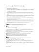
1U Tool-less Configuration (Four-Post Square Hole or Unthreaded Round Hole) To install the Dell ReadyRails system using the 1U tool-less configuration, follow these steps. 1. With the ReadyRails flange ears facing outward, place one rail between the left and right vertical posts. Align and seat the back flange rail pegs in the back vertical post flange. To see how the pegs appear in both the square and unthreaded round holes, see item 1 in the following figure. 2.
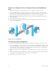
Figure 2. Two-Post Flush-Mount Configuration Two-Post Center-Mount Configuration To install the Dell ReadyRails system using the two-post center-mount configuration, follow these steps. 1. Slide the plunger bracket rearward until it clicks into place and secure the bracket to the front post flange with two user-supplied screws. See item 1 in the following figure. 2. Slide the back bracket towards the post and secure it to the post flange with two user-supplied screws. See item 2 of the following figure.
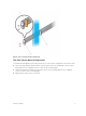
Figure 3. Two-Post Center-Mount Configuration Four-Post Threaded Configuration To install the Dell ReadyRails system using the four-post threaded configuration, follow these steps. 1. For this configuration, remove the flange ear castings from each end of the ReadyRails assemblies. To remove the two screws from each flange ear and remove each casting, use a Torx driver. See item 1 of the following figure. Retain the castings for future rack requirements. 2.
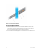
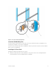
Figure 4. Four-Post Threaded Configuration Install the Z9100-ON System You can mount the system in the 1U front-rack or 1U two-post (flush and center) configurations. The following is an example of a front-rack configuration. For the 1U two-post (flush and center) configurations, slide the system into the rails in the same manner as the four-post configurations. Installing a 1U Front-Rack Configure the rails that are attached to the system. 1.
Figure 5. Attaching the Switch Rails 2. After you have installed both switch rails, line them up on the previously mounted ReadyRails and slide the switch in until it is flush with front of rack. About 3 inches before you fully insert your system, the rail locking feature engages to keep the switch from inadvertently sliding out of the rack and falling. NOTE: Do not the use the mounted ReadyRails as a shelf or a workplace.
Figure 6. Installing the Z9100–ON in a Front-Rack Configuration Attaching the Ground Cable (Recommended) Depending on the type of Z9100–ON system you have, to attach a ground cable to the chassis, you will need one of the included M3 or M4 screws. The system ships with one of the following two configurations: • One threaded hole using an included M3 screw. • Two threaded holes using one of the two included M4 screws. In both configurations, the ground cable is not included.
1. Remove the ground cable from the shipping bag and cut it to the desired length. The cable length must facilitate the proper operation of fault interrupt circuits. Dell Networking recommends using the shortest cable route allowable. 2. To attach the ground cable, use one of the following: • Using one threaded M3 hole, attached the ground cable to the lug using an M3 screw with a captive internal tooth lock washer, as shown. Torque the screw to 20 in-lbs.
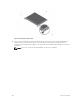
Installing AC or DC Power Supplies 1. Remove the PSU from the electro-static bag. 2. Remove the PSU slot cover from the Z9100-ON. 3. Use the grab handle to slide the PSU into the switch PSU slot. The PSU slot is keyed such that the PSU can only be fully inserted in one orientation. Figure 8. Install the AC or DC Power Supply Unit The PSU is on the right. 4. Attach the power cables (AC 3 prong or DC wiring) from the switch PSU to the external power source.
Figure 10. DC Power Connector and Wiring Block 1. Screws 2. Wiring Block 3. Power Connector To connect a DC PSU to the site’s DC power source, follow these steps: 1. Strip 1/2 inches of insulation from each of the power connector’s wires (red and black), as shown. 2. Insert each of the power connector’s bare wire lengths into the wiring block. Insert red into one hole and black into the other hole, as shown. 3.
NOTE: To remove the power connector from a DC PSU, squeeze the levers on both sides of the connector. Doing so disengages the power connector’s clamps. While continuing to squeeze, pull the power connector from the DC PSU socket. Installing a Fan Module 1. Remove the fan module from the shipping box. 2. Use the grab handle to slide the module into the switch fan slot. Figure 11. Install the Fan Module The fan module is on the left. CAUTION: DO NOT mix airflow directions.
Supply Power and Power Up the System Supply power to the Z9100–ON after the chassis is mounted in a rack or cabinet. Dell Networking recommends re-inspecting your system prior to powering up. Verify that: • The equipment is properly secured to the rack. • The equipment rack is properly mounted and grounded. • The ambient temperature around the unit (which may be higher than the room temperature) is within the limits specified for the Z9100–ON. • There is sufficient airflow around the unit.
the site that causes an increase in temperature and/or particulate matter in the air might affect performance (for example, new equipment installation). After Installing the Z9100–ON After you have securely installed and powered on the Z9100-ON, to configure your system, see your ONIE-compatible operating system documentation.
3 Dell Networking OS To initially configure the Dell Networking operating system (OS), use the following sections. NOTE: This topic applies ONLY if you already have the Dell Networking OS installed on your system from the factory. If you are installing a third-party OS, see your third-party OS documentation. NOTE: For complete installation and configuration information, see the following documents at www.dell.com/support: • Dell Networking Installation Guide for the Z9100–Open Networking (ON) System.
Accessing the Console The RS-232 console port is on the right-hand side of the Z9100–ON system as you face the PSU side of the chassis, as shown in the following illustration. Figure 12. Z9100–ON RS-232 Console Port CAUTION: Ensure that any equipment attached to the serial port can support the required 115200 baud rate. NOTE: You must have a password configured on a virtual terminal line before you can Telnet into the Z9100–ON system.
Z9100-ON Console Port RJ-45 to RJ-45 Rollover Cable RJ-45 to RJ-45 Rollover Cable RJ-45 to DB-9 Adapter Terminal Server Device Signal RJ-45 Pinout RJ-45 Pinout DB-9 Pin Signal TxD 3 6 2 RxD GND 4 5 5 GND GND 5 4 5 GND RxD 6 3 3 TxD NC 7 2 4 DTR CTS 8 1 7 RTS Default Configuration When you install the Dell Networking OS onto your Z9100–ON system, it is not configured when you power up for the first time (except for the default host name, which is Dell).
CONFIGURATION mode hostname name Accessing the System Remotely You can configure the Z9100–ON system to be accessed remotely by Telnet. The system has a dedicated management port and a management routing table that is separate from the IP routing table. 1. Configure an IP address for the management port (XXXConfiguring the Management Port IP Address). 2. Configure a management route with a default gateway (XXXConfiguring the Management Route). 3.
Configuring the Enable Password Access EXEC Privilege mode using the enable command. EXEC Privilege mode is unrestricted by default. As a basic security measure, configure a password. There are two types of enable passwords: • Enable password — stores the password in the running/startup configuration using a data encryption standard (DES)-encryption method. • Enable secret — stores the password in the running/startup configuration using a stronger, MD5encryption method.
interface vlan vlan-id 2. Enable an interface to include the IEEE 802.1Q tag header. INTERFACE mode tagged interface — Enter the following keywords and slot/port or number information: • For a 1-Gigabit Ethernet interface, enter the keyword GigabitEthernet then the slot/port information. • For a Port Channel interface, enter the keywords port-channel then a number. The range is from 1 to 128.
INTERFACE mode ip address ip-address mask [secondary] Connect the Z9100–ON to the Network After you have completed the hardware installation and software configuration for the Z9100–ON system, connect to your company network by following your company’s cabling requirements.
Technical Specifications 4 This chapter lists the Z9100–ON specifications. NOTE: Operate the system at an ambient temperature not higher than 113°F (45°C). CAUTION: Lithium Battery Caution: To avoid the possibility of an explosion, always replace the battery correctly. NOTE: Replace the battery only with the same or an equivalent type. Dispose of the batteries according to the manufacturer's instructions. Table 3. Z9100–ON Chassis Physical Design Parameter Specifications Height 1.
Table 5. AC Power Requirements Parameter Specifications Power Supply 100–240 VAC 50/60 Hz Maximum Power Consumption 606 Watts Typical Power Consumption 288 Watts Table 6. DC Power Requirements Parameter Specifications Minimum/maximum input voltage range –48, –60V DC, 32A Max Input power at full load −40.5V/970W −48V/930W −60V/ 950W (without fan) −40.5V/980W −48V/940W −60V/ 960W (with fan) Input current at full load −40.5V/23.8A −48V/19.0A −60V/ 15.6A (without fan) −40.5V/24.0A −48V/19.