
Deployment Guide


49 VCF on VxRail Multirack Deployment using BGP EVPN
8.2 Create uplink profiles and the network I/O control profile
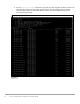
Table 9 shows the values that are used for the corresponding uplink profiles that the uplink transport zones
use.
Uplink profiles
Name
Teaming – teaming
policy
Teaming – active
uplink
Transport VLAN
MTU
esxi-w02-uplink-profile
Load Balance Source
uplink-1, uplink-2
2500
9000
sfo01-w-uplink01-profile
Failover Order
uplink-1
1647
9000
sfo01-w-uplink02-profile
Failover Order
uplink-2
1648
9000
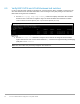
8.3 Create the NSX-T segments for system, uplink, and overlay traffic
Table 10 shows the values that are used that are for the required uplink segments. The system and overlay
segments were automatically created by VCF on VxRail.
Uplink profiles
Segment name
Uplink and type
Transport zone
VLAN
sfo01-w-nvds01-uplink01
Isolated – No logical connections
vlan-tz-<GUID>
0-4094
sfo01-w-nvds01-uplink02
Isolated – No logical connections
vlan-tz-<GUID>
0-4094
sfo01-w-uplink01
Isolated – No logical connections
sfo01-w-uplink01
1647
sfo01-w-uplink02
Isolated – No logical connections
sfo01-w-uplink02
1648
8.4 Create an NSX-T edge cluster profile
Table 11 shows the values that are used for the required edge cluster profile.
Edge cluster profile settings
Setting
Value
Name
sfo01-w-edge-cluster01-profile
BFD Probe
1000
BFD Allowed Hops
255
BFD Declare Dead Multiple
3