Dell EMC PowerSwitch Z9264F-ON Installation Guide December 2019
Notes, cautions, and warnings NOTE: A NOTE indicates important information that helps you make better use of your product. CAUTION: A CAUTION indicates either potential damage to hardware or loss of data and tells you how to avoid the problem. WARNING: A WARNING indicates a potential for property damage, personal injury, or death. © 2017 - 2019 Dell Inc. or its subsidiaries. All rights reserved. Dell, EMC, and other trademarks are trademarks of Dell Inc. or its subsidiaries.
Contents 1 About this guide........................................................................................................................... 5 Related documents............................................................................................................................................................... 5 Information symbols..............................................................................................................................................................
AC or DC power supply replacement................................................................................................................................29 DC power supply to power source connection............................................................................................................... 30 7 Fans...........................................................................................................................................31 Components.................................
1 About this guide This guide provides site preparation recommendations, step-by-step procedures for rack mounting and desk mounting your switch, inserting modules, and connecting to a power source. CAUTION: To avoid electrostatic discharge (ESD) damage, wear grounding wrist straps when handling this equipment. NOTE: Only trained and qualified personnel can install this equipment. Read this guide before you install and power up this equipment. This equipment contains two power cords.
NOTE: The Warning icon signals information about hardware handling that could result in injury. NOTE: The ESD Warning icon requires that you take electrostatic precautions when handling the device.
2 Z9264F-ON switch The following sections describe the Dell EMC Z9264F-ON switch: Topics: • • • • • • • Introduction Features Physical dimensions LED display Prerequisites Z9264F-ON switch configurations Luggage tag Introduction The Z9264F-ON switch is a two rack unit (RU), full-featured, fixed form-factor top-of-rack (ToR) and end-of-row 1/10/25/40/50/100 GbE switch. In addition, the Z9264F-ON supports two SFP+ ports at 1/10 Mbps with 10 GbE multi-mode and single-mode options.
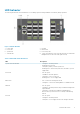
Figure 3. Z9264F-ON PSU-side view 1. Fan units 2. PSU units Features The Z9264F-ON switch offers the following features: • • • • • • • • • • Sixty-four QSFP28 ports that support 1, 10, 25, 40, 50, and 100 GbE Two SFP+ that support 1 and 10 GbE One MicroUSB type-B console port One RJ-45 serial console port One serial management USB type-A port for more file storage Denverton C3538 4-Core CPU system with 16 GB DDR4 memory and 32 GB SSD storage.
LED behavior The following Z9264F-ON switch LED behavior is seen during open networking installation environment (ONIE) operations: Figure 4. Z9264F-ON LEDs 1. 3. 5. 7. Locator LED Power LED System LED Stack ID LED 2. 4. 6. 8. Fan LED Master LED Port activity LED Top: RJ-45 Ethernet Console Port LED. Bottom: RJ-45 Ethernet Management Port LED: Left is link; right is activity Table 1.
LED Description • • • Flashing yellow—PSU warning event; power continues to operate Flashing green, 1.0Hz—Standby mode Flashing green, 0.5Hz—AC power cord unplugged LOCATOR LED/System Beacon • • Off—Locator function disabled Flashing blue—Locator function enabled 7-Segment LED for stacking • • Off—No power Solid green—Hex digit representing the stack unit ID RJ-45 Ethernet Port LED • • Off—no Ethernet activity detected Solid green—Ethernet activity detected Table 2.
LED Link/Activity LED—2x50G mode Description • • Solid yellow—Link operating at a lowr speed, 4x10G port Flashing yellow, 1 second on/off—Port beacon • • • • Off—No link Solid yellow—Link operating at a lower speed, 2x50G port Flashing yellow—Port activity at a lower speed, 2x50G port Flashing yellow, 1 second on/off—Port beacon Prerequisites The following is a list of components that are required and optional for successful switch installation: NOTE: For detailed installation instructions, see Site p
Figure 5. Z9264F-ON luggage tag 1. SVC Tag 3. PPID 12 Z9264F-ON switch 2. MAC Address 4.
3 Site preparations The Z9264F-ON switch is suitable for installation as part of a common bond network (CBN). You can install the switch in: • • • Network telecommunication facilities Data centers Other locations where the National Electric Code (NEC) applies For more information about switch specifications, see Specifications. NOTE: Install the switch into a rack or cabinet before installing any additional components such as cables or optics.
Rack mounting When you prepare your equipment rack, ensure that the rack is grounded. Ground the equipment rack to the same ground point the power service in your area uses. The ground path must be permanent. Switch ground Dell EMC recommends grounding your switch. Use the Z9264F-ON switch in a CBN. For more information, see Ground lug assembly. Fans and airflow The Z9264F-ON switch fans support two airflow options: normal and reverse.
NOTE: ESD damage can occur when components are mishandled. Always wear an ESD-preventive wrist or heel ground strap when handling the Z9264F-ON switch and accessories. After you remove the original packaging, place the Z9264F-ON switch and components on an anti-static surface.
4 NEBS compliance For your switch to be network equipment building system (NEBS) compliant, follow the instructions detailed in this section. To be NEBs compliant, orient your switch in the rack so that the air inlet is from the front aisle and the air exhaust is to the rear aisle.
Figure 6. Ground lug assembly 1. Remove the two installed M4 screws from the lower-left side of your switch. NOTE: Keep these screws. 2. Remove the bracket assembly from the shipping bag. 3. Measure and cut a length of ground wire sufficient to reach between the system-installed ground lug assembly and your rack ground point. 4. Crimp the ground cable to the ground lug assembly. a) Coat the bare end of the wire with an antioxidant compound. b) Insert the end of the wire into the ground lug.
Figure 8. Ground lug assembly attached 8. Attach the other end of the ground wire to your rack ground point. 9. Install your switch into your rack using the Z9264F-ON switch installation.
5 Z9264F-ON switch installation To install the Z9264F-ON switch, complete the installation procedures in the order presented in this chapter. Always handle the switch and components with care. Avoid dropping the switch or its field replaceable units (FRUs). NOTE: ESD damage can occur if components are mishandled. Always wear an ESD-preventive wrist or heel ground strap when handling the Z9264F-ON switch and components.
Ground lug assembly Before you install the switch into a rack, install the ground (GND) lug assembly. NOTE: For AC-powered switches, although the third conductor of the AC power cable provides a ground path, Dell EMC recommends grounding your switch with a dedicated ground wire. You can order an AC ground lug separately. NOTE: For a DC-powered switch, the only way to safely ground your switch is to attach a dedicated ground wire.
Figure 10. Ground lug assembly attached 7. Attach the GND lug bracket assembly to your switch using the two removed screws, as shown. Torque the M4 screws to ±8–10 in-lbs. Figure 11. Ground lug assembly attached 8. Attach the other end of the ground wire to your rack ground point. 9. Install your switch into your rack using the Z9264F-ON installation instructions.
2. Unscrew the tool-less feature pins from each end of both rack rails. Use a standard slotted screw driver to remove the tool-less feature pins. In this illustration, the tool-less feature pins are on the right side of the rail and the tool-less feature is on the left side of the rail. Figure 12. Remove tool-less feature 3. Pull on the tool-less features to remove them from the rack rails. 4.
• Do not mount the equipment with the fan panel facing in the downward position. 1. Align the system with the rails, and slide the system into the rack. 2. Tighten the screws on each side of the front panel, items 1 and 2. To remove the system from the rack, loosen the screws and slide the system out of the rack. Figure 13. Z9264F-ON installation 1. Extra screws to restrict front-back movement of the switch. 2. Main screw 2RU front-rack installation Configure the rails that are attached to the switch.
Figure 14. Front rack installation NOTE: Do not the use the mounted rack rails as a shelf or a workplace. 3. Tighten the two thumbscrews and rack screws. To remove the switch from the rack or cabinet, press in the two side-release bars on the switch simultaneously and slide the switch forward. Optics installation The Z9264F-ON switch has QSFP28 and SFP+ optical ports. For a list of supported optics, see the specification sheets at www.dell.com/support or contact your Dell EMC Sales representative.
Switch start-up Supply power to the Z9264F-ON switch after it is mounted in a rack or cabinet. Dell EMC recommends reinspecting your switch before starting it up. Verify the following: • • • • • • Optional: The equipment is properly secured to the rack and properly grounded. Optional: The equipment rack is properly mounted and grounded. The ambient temperature around the unit, which may be higher than the room temperature, is within the limits that are specified for the Z9264F-ON switch.
For more information, see Switch power-up. After switch placement After you have securely installed and powered on the Z9264F-ON switch: • • • 26 If you are using Dell EMC software, see switch documentation at www.dell.com/support. If you need ONIE information, see ONIE documentation at www.onie.org. If you are using third-party software, see your third-party documentation.
6 Power supplies The Z9264F-ON switch ships with two AC or DC power supplies. The two PSUs have two air-flow directions, normal and reverse. Normal is from the I/O-side to the PSU-side. Reverse is from the PSUside to the I/O-side. The PSUs are field replaceable. When running with full redundancy—two power supplies installed and running—you can remove and replace one PSU without disrupting traffic. The DC PSUs are rated -48 to -60VDC, 32A minimum, Tma=45°C, and 500m altitude operation.
The PSUs have an integrated fan, which you cannot replace individually; if the fan integrated in a PSU fails, you must replace the entire PSU. You can replace the fan trays individually. For fan tray replacement procedures, see Fans. WARNING: Prevent exposure and contact with hazardous voltages. Do not attempt to operate this switch with the safety cover removed. CAUTION: Remove the power cable from the PSU before removing the PSU.
Figure 16. Z9264F-ON PSU installation • • 1—PSU 2—Orange release tab 4. Plug in the appropriate AC 3-prongs cable from the switch PSU to the external power source. 5. Repeat steps 1 through 4 if you have a redundant PSU using the second PSU slot on the Z9264F-ON switch. NOTE: The Z9264F-ON switch powers up when you connect the cables between the power supply and the power source. AC or DC power supply replacement CAUTION: Disconnect the power cable before removing the power supplies.
DC power supply to power source connection Each DC powered switch comes with a set containing a prewired, 3-inch 8 AWG, power supply connector and a four-screw wiring block. One set is provided for each DC PSU. Figure 17. DC power connector and wiring block 1. 3. 5. 7. DC wire RTN Captive screws (2) PSU status LED DC wire –48V 2. DC power connector 4. Orange tab 6. DC power socket 1. Strip 0.5 inches of insulation from each of the power connector’s wires, RTN and –48V. 2.
7 Fans The Z9264F-ON switch comes from the factory with two PSUs and four fan modules installed in the switch. The fan modules and the power supplies, which have integrated fans, are hot-swappable. In addition to the power supply modules, you can order and install fan modules separately. The Z9264F-ON switch supports two airflow direction options. Do not mix airflow types in a switch; you can use only a single airflow direction in a switch.
Fan module replacement To request a hardware replacement, see Dell EMC support. CAUTION: Complete the following steps within one minute or the switch temperature could rise above safe thresholds and the switch could shut down: 1. Slide the fan module out of the bay. 2. Slide the replacement module into the bay. Fan air filter replacement Environmental factors can decrease the amount of time required between air filter replacements. Check the environmental factors regularly.
8 Management ports Besides the 10/100/1000Base-T RJ-45 ports, the Z9264F-ON switch provides several ports for management and storage. NOTE: The output examples in this section are for reference only. Your output may vary. Topics: • • • • • RS-232 console port access MicroUSB-B console port access USB storage mount Before you install an OS ONIE service discovery RS-232 console port access The RS-232 console port is on the I/O-side of the Z9264F-ON switch. Figure 19.
• No flow control MicroUSB-B console port access The MicroUSB-B console port is on the I/O side of the switch. NOTE: The Z9264F-ON switch uses the Silicon Labs CP2109 USB-B chip. To find the correct USB-B universal asynchronous receiver-transmitter (UART) driver, see https://www.silabs.com/products/development-tools/ software/usb-to-uart-bridge-vcp-drivers.
For USB storage: Disk /dev/sdb: 30.9 GB, 30942946304 bytes 64 heads, 32 sectors/track, 29509 cylinders Units = cylinders of 2048 * 512 = 1048576 bytes Device Boot Start End Blocks Id System 3. Mount the device /dev/sdb to the /mnt/usb directory. ONIE:/ # mount -t vfat /dev/sdb /mnt/usb NOTE: The following message displays if the /mnt/usb directory is missing: mount: mounting /dev/sdb on /mnt/usb failed: No such file or directory.
NOTE: After you have securely installed and powered on the Z9264F-ON switch, to configure your switch, see your third-party ONIE-compatible OS or the Dell EMC OS documentation. ONIE service discovery ONIE attempts to locate the installer through several discovery methods. To download and run an installer, the ONIE Service Discovery feature follows these steps in order and uses the first successful method found: 1.
9 Specifications This section lists the Z9264F-ON switch specifications. CAUTION: Operate the product at an ambient temperature not higher than 45°C (113°F). CAUTION: Lithium Battery Caution: There is a danger of explosion if the battery is incorrectly replaced. Replace only with same or equivalent type of battery. Dispose of the batteries according to the manufacturer's instructions. NOTE: For RoHS information, see Restricted Material Compliance.
Parameter Specifications Operating humidity 5% to 90% (RH), non-condensing Storage temperature –40°C to 70°C (–40°F to 158°F) Storage humidity 5% to 90%, non-condensing Maximum thermal output 470 W = 1603.7 BTU/Hr Maximum operational altitude 5,000 feet (1,524 meters) Maximum non-operational altitude 39,370 feet (12,000 meters) Shock Dell EMC Spec SV0115 Table 7. AC power requirements Parameter Specifications Power supply 100–240 VAC 50/60 Hz Maximum current draw per switch 4.7A/3.
Properly shielded and grounded cables and connectors must be used in order to meet FCC emission limits. Dell EMC is not responsible for any radio or television interference caused by using other than recommended cables and connectors or by unauthorized changes or modifications in the equipment. Unauthorized changes or modification could void the user’s authority to operate the equipment. This device complies with Part 15 of the FCC Rules.
NOTE: Use the AC power cords with Dell EMC equipment only. Do not use Dell EMC AC power cords with any unauthorized hardware. Figure 22. Japan: warning label Korean certification of compliance Figure 23. Korean certification of compliance Figure 24.
China warning Figure 25. China warning Safety standards and compliance agency certifications • CUS UL 60950-1, 2nd Edition • • • • • • • • • Meets or exceeds Hi Pot and Ground Continuity testing per UL 60950-1. CSA 60950-1-03, 2nd Edition EN 60950-1, 2nd Edition EN 60825-1, 1st Edition EN 60825-1 Safety of Laser Products—Part 1: Equipment Classification Requirements and User’s Guide EN 60825-2 Safety of Laser Products—Part 2: Safety of Optical Fibre Communication Systems FDA Regulation 21CFR 1040.
• • • • • • • • EN 61000-3-3 Voltage Fluctuations and Flicker EN 61000-4-2 ESD EN 61000-4-3 Radiated Immunity EN 61000-4-4 EFT EN 61000-4-5 Surge EN 61000-4-6 Low Frequency Conducted Immunity EN 61000-6-1 EN 61000-4-11 Voltage Dips/Interruptions Product recycling and disposal You must recycle or discard this switch according to applicable local and national regulations. Dell EMC encourages owners of information technology (IT) equipment to responsibly recycle their equipment when it is no longer needed.
10 Dell EMC support The Dell EMC support site provides documents and tools to help you effectively use Dell EMC equipment and mitigate network outages. Through the support site you can obtain technical information, access software upgrades and patches, download available management software, and manage your open cases. The Dell EMC support site provides integrated, secure access to these services. To access the Dell EMC support site, go to www.dell.com/support/.