
Install Guide

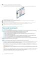

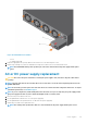

2. Unscrew the tool-less feature pins from each end of both rack rails.
Use a standard slotted screw driver to remove the tool-less feature pins.
In this illustration, the tool-less feature pins are on the right side of the rail and the tool-less feature is on the left side of the rail.
Figure 12. Remove tool-less feature
3. Pull on the tool-less features to remove them from the rack rails.
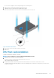
4. Mount the rack rails directly to the front and back of the rack using two screws and clip nuts at the four mounting points.
5. Attach the inner switch rails to the switch.
Line up the rail with the mounting heads and attach the rail to the switch. For more information, see2RU front-rack installation.
6. Align the switch rails with the rack rails and slide the switch into the rack until it is flush with the front of the rack.
7. Tighten the screws on the rails to secure the switch in the rack, if needed.
To install the switch in a rack you do not intend to ship, see Four-post rack mount.
Four-post rack mount
Rack mounting safety considerations
NOTE:
To prevent bodily injury when mounting or servicing this unit in a rack, take special precautions to ensure that
the system remains stable. The following guidelines are provided to ensure your safety:
• If your chassis is the only unit in the rack, mount it at the bottom of the rack.
• When mounting this unit in a partially filled rack, load the rack from the bottom to the top with the heaviest
component at the bottom of the rack.
• If the rack comes with stabilizing devices, install the stabilizers before mounting or servicing the unit in the rack.
• If the chassis ships with blanks, remove the blanks from each slot before lifting the chassis.
NOTE: These instructions are a condensed reference. Read the safety instructions in your
Safety, Environmental, and
Regulatory
information booklet before you begin.
NOTE: The illustrations in this document are not intended to represent a specific switch.
• Rack loading—Overloading or uneven loading of racks may result in shelf or rack failure, possibly damaging the equipment and causing
personal injury. Stabilize racks in a permanent location before loading begins. Mount the components starting at the bottom of the
rack, then work to the top. Do not exceed the load rating for your rack.
• Power considerations—Connect only to the power source specified on the unit. When you install multiple electrical components in a
rack, ensure that the total component power ratings do not exceed the circuit capabilities. Overloaded power sources and extension
cables present fire and shock hazards.
• Elevated ambient temperature—If you install the switch in a closed rack assembly, the operating temperature of the rack environment
may be greater than the room ambient temperature. Use care not to exceed the 45°C (113°F) maximum ambient temperature of the
switch.
• Reduced airflow—Do not compromise the amount of airflow that is required for safe operation of the equipment. Install the equipment
in the rack so that the equipment constantly has the correct amount of airflow surrounding it.
• Reliable earthing—Maintain reliable earthing of rack-mounted equipment. Pay particular attention to the supply connections other
than the direct connections to the branch circuit, for example: use of power strips.
22
Z9264F-ON switch installation