
Install Guide


LED behavior
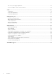
The following Z9264F-ON switch LED behavior is seen during open networking installation environment (ONIE) operations:
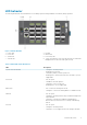
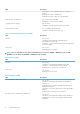
Figure 4. Z9264F-ON LEDs
1.
Locator LED 2. Fan LED
3. Power LED 4. Master LED
5. System LED 6. Port activity LED
7. Stack ID LED 8. Top: RJ-45 Ethernet Console Port LED. Bottom: RJ-45 Ethernet
Management Port LED: Left is link; right is activity
Table 1. Z9264F-ON switch LED behavior
LED Description
System Status/Health LED
• Solid green—Normal operation
• Flashing green—Booting
• Solid yellow (amber)—Critical system error
• Flashing yellow—Noncritical system error, fan failure, or power
supply failure
Power LED
• Off—No power
• Solid Green—Normal operation
• Solid yellow—POST is in process
• Flashing yellow—Power supply failed
Master LED
• Off—Switch is in Stacking Slave mode
• Solid green—Switch is in Stacking Master or Standalone mode
FAN LED
• Off—No power
• Solid green—Normal operation; fan powered and running at the
expected RPM
• Solid yellow—Fan failed—including incompatible airflow
direction when you insert the PSU or fan trays with differing
airflows
PSU LED
• Off—No power
• Solid green—Normal operation
• Solid yellow—Power supply critical event causing a shutdown
Z9264F-ON switch 9