4939tbk1.
4939tbk1.
4939tbk1.
939tbk1.book Page 2 Friday, October 8, 1999 1:22 PM ____________________ Information in this document is subject to change without notice. © 1999 Dell Computer Corporation. All rights reserved. Reproduction in any manner whatsoever without the written permission of Dell Computer Corporation is strictly forbidden. Trademarks used in this text: Dell, the DELL logo, PowerEdge, and PowerVault are trademarks of Dell Computer Corporation.
4939tbk1.book Page iii Friday, October 8, 1999 1:22 PM Use the following safety guidelines to ensure your own personal safety and to help protect your computer or storage system from potential damage. Throughout this guide, blocks of text may be accompanied by an icon and printed in bold type or in italic type.
4939tbk1.book Page iv Friday, October 8, 1999 1:22 PM $ % & 2 2" ) !"# $ % & ' ( ) *+,+% -* ,. ' % *+ %/ !* .0 # . 1 & 2% ' / * + $ +% !3 0 !* "04 * + . . 0! #+' 2 $ !"# % & ' ( *.
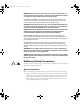
4939tbk1.book Page v Friday, October 8, 1999 1:22 PM If any of the following conditions occur, unplug the product from the electrical outlet and replace the part or contact your Dell authorized service provider: — The power cable, extension cord, or plug is damaged. — An object has fallen into the product. — The product has been exposed to water. — The product has been dropped or damaged. — The product does not operate correctly when you follow the operating instructions.
4939tbk1.book Page vi Friday, October 8, 1999 1:22 PM adapter plugs or remove the grounding prong from a cable. If you must use an extension cord, use a three-wire cord with properly grounded plugs. Observe extension cord and power strip ratings. Make sure that the total ampere rating of all products plugged into the extension cord or power strip does not exceed 80 percent of the extension cord or power strip ampere ratings limit.
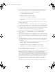
4939tbk1.book Page vii Friday, October 8, 1999 1:22 PM Observe the following precautions for rack stability and safety. Also refer to the rack installation documentation accompanying the system and the rack for specific warning and/or caution statements and procedures.
4939tbk1.book Page viii Friday, October 8, 1999 1:22 PM ! " # $% Observe the following guidelines when working with options: Do not connect or use a modem or telephone during a lightning storm. There may be a risk of electrical shock from lightning. Never connect or use a modem or telephone in a wet environment. Do not plug a modem or telephone cable into the network interface controller (NIC) receptacle.
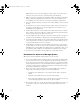
4939tbk1.book Page ix Friday, October 8, 1999 1:22 PM 3. Disconnect your computer and devices from their power sources. Also, disconnect any telephone or telecommunication lines from the computer. Doing so reduces the potential for personal injury or shock. In addition, take note of these safety guidelines when appropriate: When you disconnect a cable, pull on its connector or on its strain-relief loop, not on the cable itself.
4939tbk1.book Page x Friday, October 8, 1999 1:22 PM ! 2 # . ' For comfort and efficiency, observe the following ergonomic guidelines when you set up and use your computer system: x Position your system so that the monitor and keyboard are directly in front of you as you work.
4939tbk1.
4939tbk1.
4939tbk1.book Page xiii Friday, October 8, 1999 1:22 PM ' Before You Begin . . . . . . . . . . . . . . . . . . . . . . . . . . . . . . . . . . . . . . . . . . . . . . . . . . Recommended Tools . . . . . . . . . . . . . . . . . . . . . . . . . . . . . . . . . . . . . . . . . . . . Installing the Switch . . . . . . . . . . . . . . . . . . . . . . . . . . . . . . . . . . . . . . . . . . . . . . . . Removing the Doors From the Rack . . . . . . . . . . . . . . . . . . . . . . . . . . . . . . .
4939tbk1.
4939tbk1.book Page 1 Friday, October 8, 1999 1:22 PM ! This document provides instructions for trained service technicians installing one or more Dell PowerVault 51F Fibre Channel switches in a Dell rack.
4939tbk1.book Page 2 Friday, October 8, 1999 1:22 PM # To install the switch in the rack, perform the following tasks. The subsections that follow include instructions for performing these tasks. 1. Remove the doors from the rack, if necessary. 2. Install the slide assembly. 3. Install the switch assembly. 4. Install the cable-management arm and route the cables. 5. Replace the rack doors if you removed them.
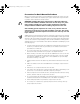
4939tbk1.book Page 3 Friday, October 8, 1999 1:22 PM & ' You may remove the front and back doors from the rack to provide access to the interior of the rack and to prevent damage to the doors while installing the kit. Use the following procedure to remove the doors. # ! " 1. Open the latch on the front door (see Figure 1-2).
4939tbk1.book Page 4 Friday, October 8, 1999 1:22 PM hinge release lever Store the two doors in an area where they will not fall over while you install the switch. ! ( ) * If you are installing the switch in a non-Dell rack, you may need to adjust the bezel position to allow the rack doors to close properly. To adjust the bezel position, perform the following steps (see Figure 1-4): 1-4 1.
4939tbk1.book Page 5 Friday, October 8, 1999 1:22 PM bezel tab back holes mounting clip 6-32 x 1/2-inch screws (4) front holes ! " # $ % + ! To install the slide assembly in the rack, perform the following steps: 1. Align the holes of the stationary and adjustable brackets with the holes in the vertical rail. The stationary brackets attach to the front of the rack. The adjustable brackets attach to the back.
4939tbk1.book Page 6 Friday, October 8, 1999 1:22 PM vertical rail tapered washers (8) 10-32 x 1/2-inch screws (8) outer slide stationary bracket adjustable bracket & ' $$ ($ )$* 2. Use four 10-32 x 1/2-inch screws and four tapered washers to install each outer slide in the rack, as shown in Figure 1-5. The screws are threaded through the washers, the rail, and into the top and bottom holes of the brackets, leaving the middle bracket holes open. 3.
4939tbk1.book Page 7 Friday, October 8, 1999 1:22 PM + # To install the switch in the rack, perform the following steps: 1. Extend both intermediate slides forward until they lock in the extended position. 2. At the front of the rack, carefully align the switch’s inner-slide rails with the intermediate slides. Slide the inner-slide rails into the intermediate slides, as shown in Figure 1-6.
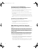
4939tbk1.book Page 8 Friday, October 8, 1999 1:22 PM + , ! 1. From the back of the rack, pull the switch out about 7 centimeters (cm) (about 3 inches). The switch should lock in place. 2. Attach the end of the cable-management arm to the inner-slide rail by inserting the two tabs into the two slots until the retaining clip snaps into place (see Figure 1-7).
4939tbk1.book Page 9 Friday, October 8, 1999 1:22 PM 3. Route the cables along the cable-management arm and secure the cables to the cable-management arm with the Velcro straps attached to the cablemanagement arm. Make sure that the cables are not pinched in the cable-management arm joints. For details on connecting the cables to the computer, see the Installation and Troubleshooting Guide. 4.
4939tbk1.
4939tbk1.
4939tbk1.book Page 2 Friday, October 8, 1999 1:22 PM ____________________ Les informations de ce document sont sujettes à modification sans préavis. © 1999 Dell Computer Corporation. Tous droits réservés. La reproduction de quelque manière que ce soit sans l’autorisation écrite de Dell Computer Corporation est strictement interdite. Marques utilisées dans ce texte : Dell, le logo DELL, PowerVault et PowerEdge sont des marques de Dell Computer Corporation.
4939tbk1.book Page iii Friday, October 8, 1999 1:22 PM " ! # # Observez les consignes de sécurité suivantes afin d'assurer votre sécurité personnelle et de protéger votre système informatique contre des dommages éventuels. $ % & ' & Dans ce guide, des blocs de texte peuvent être accompagnés d’une icône et imprimés en caractères gras ou en italique.
4939tbk1.book Page iv Friday, October 8, 1999 1:22 PM ( 9 9 D + D 9 ' D + 9 @ ( ' * , - 9 ' ) > 2 * , . /0 1 .
4939tbk1.book Page v Friday, October 8, 1999 1:22 PM - . - - Observez les précautions d'ordre général suivantes lorsque vous utilisez votre système : Observez et respectez les consignes d'entretien. Ne révisez pas un produit Dell sauf si c'est indiqué dans la documentation de votre système Dell. Si vous ouvrez ou retirez des capots dotés d'un symbole triangulaire avec un éclair, vous risquez d'être soumis(e) à des chocs électriques.
4939tbk1.
4939tbk1.book Page vii Friday, October 8, 1999 1:22 PM Pour éviter d'endommager la carte système, attendez 5 secondes après avoir arrêté le système avant de retirer un composant de la carte système ou de déconnecter un périphérique de l'ordinateur. Manipulez les piles avec précaution.
4939tbk1.book Page viii Friday, October 8, 1999 1:22 PM > 9 > 2" ! # @ 2 D > C 3 @ 9 2 REMARQUE : Les serveurs et systèmes de stockage Dell sont certifiés comme des composants à utiliser dans le boîtier de rack Dell avec le kit pour rack client Dell.
4939tbk1.book Page ix Friday, October 8, 1999 1:22 PM - % % - . % - - - Observez les consignes suivantes lorsque vous travaillez avec des options : Ne connectez ni n'utilisez un modem ou un téléphone lors d'un orage. Il peut y avoir un risque de choc électrique dû à la foudre. Ne connectez et n'utilisez jamais un modem ou téléphone dans un environnement mouillé.
4939tbk1.book Page x Friday, October 8, 1999 1:22 PM 2. Mettez-vous à la terre en touchant une surface métallique non peinte du châssis, comme le métal autour des ouvertures des emplacements des cartes à l'arrière de l'ordinateur, avant de toucher tout autre élément à l’intérieur de votre ordinateur.
4939tbk1.book Page xi Friday, October 8, 1999 1:22 PM Vous pouvez aussi prendre les mesures suivantes pour prévenir les dommages liés aux ESD (Electrostatic discharge [décharges électrostatiques]) : Lorsque vous déballez un composant sensible à l'électricité statique de sa boîte de livraison, ne retirez pas le composant de l'emballage antistatique jusqu'à ce que vous soyez prêt à installer le composant dans votre ordinateur.
4939tbk1.book Page xii Friday, October 8, 1999 1:22 PM Tenez-vous droit(e), avec vos pieds sur le sol et vos cuisses à niveau. Quand vous êtes assis(e), assurez-vous que le poids de vos jambes porte sur vos pieds et non sur l'avant de votre chaise. Réglez la hauteur de votre chaise ou utilisez un repose-pieds si nécessaire pour conserver une position correcte. Variez vos activités. Essayez d’organiser votre travail de sorte que vous n’ayez pas à taper durant de longues périodes d’affilée.
4939tbk1.book Page xiii Friday, October 8, 1999 1:22 PM Avant de commencer . . . . . . . . . . . . . . . . . . . . . . . . . . . . . . . . . . . . . . . . . . . . . . . Outils recommandés . . . . . . . . . . . . . . . . . . . . . . . . . . . . . . . . . . . . . . . . . . . . Installation du commutateur . . . . . . . . . . . . . . . . . . . . . . . . . . . . . . . . . . . . . . . . . . Retrait des portes du rack . . . . . . . . . . . . . . . . . . . . . . . . . . . . . . . . .
4939tbk1.
4939tbk1.book Page 1 Friday, October 8, 1999 1:22 PM ! !$ !$ %% & ' Ce document fournit des instructions aux techniciens de service agréés pour installer un ou plusieurs commutateurs Dell PowerVault 51F Fibre Channel dans un rack Dell.
4939tbk1.book Page 2 Friday, October 8, 1999 1:22 PM Pour installer le commutateur dans le rack, effectuez les étapes ci-après. Les soussections qui suivent comprennent des instructions pour effectuer ces tâches. 1. Retirez les portes du rack, si nécessaire. 2. Installez l’assemblage à glissière. 3. Installez l’assemblage commutateur. 4. Installez le bras de maniement de câble et acheminez les câbles. 5. Remettez les portes du rack en place si vous les avez retirées.
4939tbk1.book Page 3 Friday, October 8, 1999 1:22 PM % Vous pouvez retirer les portes avant et arrière du rack pour vous procurer accès à l’intérieur du rack et éviter d’endommager les portes durant l’installation du kit. Utilisez la procédure qui suit pour retirer les portes. ,%? , 9 " + ! # ) ) C 1. Ouvrez le loquet de la porte avant (voir la figure 2-2).
4939tbk1.book Page 4 Friday, October 8, 1999 1:22 PM 3. Répétez les étapes 1 et 2 pour retirer la porte arrière du rack. levier de dégagement de la charnière Mettez les deux portes de côté dans un endroit où elles ne risquent pas de tomber pendant que vous installez le commutateur.
4939tbk1.book Page 5 Friday, October 8, 1999 1:22 PM languette du cadre trous arrière clip de montage vis 6-32 x 1/2 pouce (4) trous avant / $ $ + 1 2 / Pour installer l’assemblage à glissière dans le rack, effectuez les étapes suivantes : 1. Alignez les trous des supports fixes et réglables avec les trous du rail vertical. Les supports fixes s’attachent à l’avant du rack. Les supports réglables s’attachent à l’arrière.
4939tbk1.book Page 6 Friday, October 8, 1999 1:22 PM rail vertical rondelles à épaisseur décroissante (8) vis 10-32 x 1/ 2 pouce (8) glissière externe support fixe support réglable & ' $$ $0 )$ 1 $ 2 2. $ Utilisez quatre vis 10-32 x 1/2 pouce et quatre rondelles à épaisseur décroissante pour installer chaque glissière externe dans le rack, comme illustré parc la figure 2-5.
4939tbk1.book Page 7 Friday, October 8, 1999 1:22 PM + Pour installer le commutateur dans le rack, effectuez les étapes suivantes : 1. Étendez les deux glissières vers l’avant jusqu’à ce qu’elles se bloquent en position étendue. 2. À l’avant du rack, alignez soigneusement les rails des glissières internes avec les glissières intermédiaires. Glissez les rails des glissières internes dans les glissières intermédiaires, comme le montre la figure 2-6.
4939tbk1.book Page 8 Friday, October 8, 1999 1:22 PM 5. Serrez les deux vis à ailettes sur le cadre afin d’empêcher le commutateur et l’assemblage à glissière de glisser hors du rack. Les vis à ailettes traversent les trous du rack et les trous au milieu des supports fixes. + 1. 3 De l’arrière du rack, tirez le commutateur d’environ 7 centimètres (cm). Le commutateur devrait se bloquer en place. 2.
39tbk1.book Page 9 Friday, October 8, 1999 1:22 PM 3. Acheminez les câbles le long du bras de maniement de câble et fixez-les au bras à l’aide des bandes Velcro prévues à cet effet sur le bras de maniement de câble. Veillez à ne pas pincer les câbles dans les articulations du bras de maniement de câble. Pour plus de précisions sur la connexion des câbles à l’ordinateur, consultez le Guide d'installation et de dépannage. 4.
4939tbk1.
4939tbk1.
4939tbk1.book Page 2 Friday, October 8, 1999 1:22 PM ____________________ Irrtümer und technische Änderungen vorbehalten. © 1999 Dell Computer Corporation. Alle Rechte vorbehalten. Nachdrucke jeglicher Art ohne die vorherige schriftliche Genehmingung der Dell Computer Corporation sind strengstens untersagt. Warenzeichen in diesem Text: Dell, das DELL-Logo, PowerEdge und PowerVault sind Warenzeichen der Dell Computer Corporation.
4939tbk1.book Page iii Friday, October 8, 1999 1:22 PM " Beachten Sie die folgenden Sicherheitsanweisungen, zur Gewährleistung der eigenen Sicherheit und um den Computer und das Speichersystem vor möglicher Beschädigung zu schützen. # * # Im diesem Handbuch sind verschiedene Textabschnitte mit einem Symbol gekennzeichnet und kursiv- oder fettgedruckt.
4939tbk1.book Page iv Friday, October 8, 1999 1:22 PM . ! 27 1 ) 2 J 1 6 L ) ! * $ J * , - 7 1 * , .
4939tbk1.book Page v Friday, October 8, 1999 1:22 PM 4 Beachten Sie die folgenden Sicherheitsmaßnahmen beim Gebrauch des Systems und bei Arbeit am Computer: Beachten Sie die folgenden Wartungshinweise. Warten Sie alle Dell Produkte nur so, wie in der Dell System-Dokumentation beschrieben. Das Öffnen und Entfernen von Abdeckungen, die mit einem Blitzsymbol innerhalb eines Dreiecks gekennzeichnet sind, kann einen elektrischen Schlag verursachen.
4939tbk1.book Page vi Friday, October 8, 1999 1:22 PM Um Beschädigungen der Systemkomponenten zu verhindern, stellen Sie sicher, daß der Spannungswahlschalter am Netzteil (falls vorhanden) den örtlichen Stromgegebenheiten entsprechend eingestellt ist: — 115 Volt (V)/60 Hertz (Hz) in den meisten nord- und südamerikanischen Ländern und einigen Ländern des Fernen Ostens, wie z.B.
4939tbk1.book Page vii Friday, October 8, 1999 1:22 PM Gehen Sie vorsichtig mit Batterien um. Batterien nie auseinanderbauen, zusammendrücken, durchlöchern, kurzschließen, in Feuer oder Wasser entsorgen oder Temperaturen von mehr als 60 Grad Celsius (140 Grad Fahrenheit) aussetzen. Versuchen Sie nicht, Batterien zu öffnen oder zu warten; ersetzen Sie Batterien nur mit für das Produkt bestimmten Batterien. Vermindern Sie die Lautstärke, bevor Sie Kopfhörer oder andere Audio-Geräte verwenden.
4939tbk1.book Page viii Friday, October 8, 1999 1:22 PM $ 1 2 % 2 " L 1 % 2 ! * & ! L 2 ! 2 % 2 ! . ! J ANMERKUNG: Der Dell Server und das Dell Speichersystem sind ausgelegt als Komponenten für den Gebrauch in Dells Rack-Schrank unter Verwendung des Dell Kunden-Rack-Bausatzes.
4939tbk1.book Page ix Friday, October 8, 1999 1:22 PM 4 5 ! " # 6 " *# 7 $% Beachten Sie die folgenden Richtlinien, wenn Sie mit Optionen arbeiten: Ein Modem oder Telefon nie während eines Gewitters anschließen oder benutzen. Es besteht die Gefahr eines elektrischen Schlages durch Blitzeinschlag. Ein Modem oder Telefon nie in einer feuchten Umgebung anschließen oder benutzen.
4939tbk1.book Page x Friday, October 8, 1999 1:22 PM 2. Erden Sie sich selbst, indem Sie eine unbeschichtete Metallfläche am Systemgehäuse berühren (z.B. den Metallrahmen der Kartensteckplatzöffnungen auf der Rückseite des Systems), bevor Sie etwas im Inneren des Systems berühren. Wiederholen Sie während der Arbeit im Inneren des Systems diese Erdung regelmäßig, um statische Aufladungen, die die internen Komponenten beschädigen könnten, abzuleiten. 3.
4939tbk1.book Page xi Friday, October 8, 1999 1:22 PM Transportieren Sie anfällige Komponenten in einem antistatischen Behälter oder in einer antistatischen Verpackung. Alle anfälligen Komponenten in einer statikfreien Umgebung handhaben. Wenn möglich antistatische Fußboden- und Arbeitsplatzunterlagen verwenden.
4939tbk1.book Page xii Friday, October 8, 1999 1:22 PM Variieren Sie Ihre Arbeitsaktivitäten. Versuchen Sie, Ihre Arbeit so einzuteilen, daß Sie nie für längere Zeit tippen müssen. Wenn Sie das Tippen beenden, versuchen Sie etwas zu tun, wozu Sie beide Hände gebrauchen.
4939tbk1.book Page xiii Friday, October 8, 1999 1:22 PM Bevor Sie anfangen . . . . . . . . . . . . . . . . . . . . . . . . . . . . . . . . . . . . . . . . . . . . . . . . . 3-1 Empfohlene Werkzeuge. . . . . . . . . . . . . . . . . . . . . . . . . . . . . . . . . . . . . . . . . . 3-1 Schalter einbauen . . . . . . . . . . . . . . . . . . . . . . . . . . . . . . . . . . . . . . . . . . . . . . . . . . 3-2 Türen vom Rack entfernen. . . . . . . . . . . . . . . . . . . . . . . . . . . . . .
4939tbk1.
4939tbk1.book Page 1 Friday, October 8, 1999 1:22 PM % ( ) ! Dieses Dokument enthält Anleitung für geschulte Servicetechniker zur Installation von einem oder mehrerer Dell PowerVault 51F Glasfaserkanalschalter in einem Dell-Rack.
4939tbk1.book Page 2 Friday, October 8, 1999 1:22 PM ! Um den Schalter in das Rack einzubauen, die folgenden Schritte ausführen. Die nachfolgenden Unterabschnitte enhalten die Anleitungen zur Ausführung dieser Schritte. 1. Türen vom Rack abnehmen (falls nötig). 2. Schubmontagesatz installieren. 3. Schaltermontagesatz installieren. 4. Kabelmanagementarm installieren und Kabel verlegen. 5. Racktüren wieder anbringen (falls zuvor entfernt).
4939tbk1.book Page 3 Friday, October 8, 1999 1:22 PM 5 Sie können die Türen von Rack entfernen, um besseren Zugang zum Inneren des Rack zu haben und die Beschädigung der Türen zu vermeiden. Die folgende Vorgehensweise benutzen. . %1 H L7 ! ! " & 7K & J 27 " 1 ) " J ! 1. Öffnen Sie den Riegel an der vorderseitigen Tür (siehe Abbildung 3-2).
4939tbk1.book Page 4 Friday, October 8, 1999 1:22 PM 3. Schritte 1 und 2 Wiederholen, um die hintere Tür des Rack abzunehmen. Scharnierfreigabehebel )) $ 6 8 Die zwei Türen an einem Ort aufbewahren, an dem sie nicht umfallen können, während Sie den Schalter installieren. ) % ( Falls Sie den Schalter nicht in ein Dell-Rack einbauen, müssen Sie u.U. die Blendenposition neu justieren, damit sich die Türen korrekt schließen lassen (siehe Abbildung 3-4): 3-4 1.
4939tbk1.book Page 5 Friday, October 8, 1999 1:22 PM Blendennase hintere Löcher mounting clip vordere Löcher 6-32 x 1/2-Zoll Schrauben (4) )) $ "$ ! * Um den Schubmontagesatz zu installieren, die folgenden Schritte ausführen: 1. Die Löcher auf den starren und justierbaren Halterungen auf die Löcher der vertikalen Schiene ausrichten.
4939tbk1.book Page 6 Friday, October 8, 1999 1:22 PM Senkrechte Schiene konische Unterlegscheiben (8) 10-32 x 1/2-Zoll Schrauben (8) äußere Gleitschiene starre Halterung justierbare Halterung )) $ & ( ) # 2. $$ Vier 10-32 x 1/2-Zoll Schrauben und vier konische Unterlegscheiben benutzen, wie in Abbildung 3-5 gezeigt.
4939tbk1.book Page 7 Friday, October 8, 1999 1:22 PM Um den Schalter in das Rack einzubauen, die folgenden Schritte ausführen: 1. Beide Zwischenschienen nach vorne herausziehen, bis sie sich in vollständig ausgefahrener Position befinden. 2. An der Vorderseite des Racks die inneren Gleitschiene des Schalters vorsichtig auf die Zwischenschienen ausrichten. Die inneren Gleitschienen in die Zwischenschienen schieben, wie in Abbildung 3-6 gezeigt.
4939tbk1.book Page 8 Friday, October 8, 1999 1:22 PM 5. Die zwei Rändelschrauben an der Blende festdrehen damit der Schalter und der Schubmontagesatz nicht aus dem Rack herausgleiten kann. Die Rändelschrauben werden durch die Löcher im Rack und in die mittleren Löcher der starren Halterungen gesteckt. & : 5 1. Von der Rückseite des Racks aus den Schalter ca. 7 Zentimeter (cm) herausziehen. Der Schalter sollte einrasten. 2.
4939tbk1.book Page 9 Friday, October 8, 1999 1:22 PM Nasen Schlitze Kabelführungsarm KlettverschlußStreifen innere Gleitschiene Rändelschraube Halteklemme Sicherheitsfreigabehebel )) $ - ) $86 $$ 3. Leiten Sie die Kabel entlang des Kabelführungsarms und befestigen Sie sie dort mit den am Kabelführungsarm angebrachten Klettverschlüssen. Stellen Sie sicher, daß die Kabel nicht von den Gelenken des Kabelführungsarms eingeklemmt sind.
4939tbk1.book Page 10 Friday, October 8, 1999 1:22 PM 5. Die Rändelschraube am Kabelführungsarm festziehen. Die Rändelschraube paßt durch das Loch im Rack und durch das mittlere Loch der justierbaren Halterung. 5 # Um die Türen wieder am Rack anzubringen, den folgenden Schritten folgen. . %1 H & 7K & J L7 ! ! " 1 " J ! ! ! 1.
4939tbk1.
4939tbk1.book Page 2 Friday, October 8, 1999 1:22 PM ____________________ La información contenida en este documento puede modificarse sin aviso previo. © 1999 Dell Computer Corporation. Quedan reservados todos los derechos. Queda estrictamente prohibida la reproducción de este documento en cualquier forma sin la autorización por escrito de Dell Computer Corporation.
4939tbk1.book Page iii Friday, October 8, 1999 1:22 PM ! " ! ! Observe las pautas de seguridad siguientes para garantizar su seguridad personal y para proteger su ordenador o sistema de almacenamiento contra un daño potencial. & & A lo largo de esta guía, encontrará secciones de texto que pueden estar acompañadas por un icono e impresas en negritas o en itálicas.
4939tbk1.book Page iv Friday, October 8, 1999 1:22 PM * , - * , . /0 1 *.
4939tbk1.book Page v Friday, October 8, 1999 1:22 PM Si ocurre alguna de las condiciones siguientes, desenchufe el producto del tomacorriente y reemplace la pieza o póngase en contacto con su proveedor de servicio autorizado Dell: — El cable de alimentación, cable de extensión o enchufe está dañado. — Ha caído un objeto en el aparato. — El aparato ha estado en contacto con el agua. — El aparato se ha caído o se ha dañado.
4939tbk1.book Page vi Friday, October 8, 1999 1:22 PM cable de alimentación que esté aprobado para el uso en su país. El cable de alimentación debe tener valor nominal para el producto y para el voltaje y corriente marcada en la etiqueta de los valores nominales eléctricos del producto. El valor nominal de voltaje y corriente del cable debe ser mayor que los valores nominales marcados en el producto.
4939tbk1.book Page vii Friday, October 8, 1999 1:22 PM % Observe las pautas de seguridad adicionales para su sistema siguientes: A menos que su documentación de instalación y/o solución de problemas lo permita específicamente, no retire las cubiertas del gabinete, intente pasar por alto los enclavamientos de seguridad ni acceda a ninguno de los componentes dentro del sistema.
4939tbk1.book Page viii Friday, October 8, 1999 1:22 PM seguridad. Es la responsabilidad del cliente solicitar a una agencia de seguridad certificada que evalúe la combinación final de sistemas Dell y paquetes de estantes para ser utilizados en otras marcas de gabinetes de estantes. Los paquetes de estantes de sistemas están diseñados para instalarse en un estante Dell por técnicos capacitados de servicio.
4939tbk1.book Page ix Friday, October 8, 1999 1:22 PM Desconecte el cable del módem antes de abrir un gabinete de producto, tocar o instalar componentes internos o tocar un cable o enchufe de módem no aislado. No use una línea telefónica para informar de un escape de gas mientras está en las cercanías de la fuga.
4939tbk1.book Page x Friday, October 8, 1999 1:22 PM lengüetas de seguro antes de desconectar el cable. Cuando separe conectores, manténgalos alineados para evitar doblar las patas de conexión. Asimismo, antes de conectar un cable, asegúrese de que los conectores estén orientados y alineados correctamente. Maneje con cuidado los componentes y las tarjetas. No toque los componentes ni los contactos de las tarjetas. Sostenga las tarjetas por sus bordes o por su soporte metálico de montaje.
4939tbk1.
4939tbk1.
4939tbk1.book Page xiii Friday, October 8, 1999 1:22 PM Antes de comenzar . . . . . . . . . . . . . . . . . . . . . . . . . . . . . . . . . . . . . . . . . . . . . . . . . 4-1 Herramientas recomendadas . . . . . . . . . . . . . . . . . . . . . . . . . . . . . . . . . . . . . . 4-1 Instalación del interruptor . . . . . . . . . . . . . . . . . . . . . . . . . . . . . . . . . . . . . . . . . . . . 4-2 Retiro de las puertas del estante . . . . . . . . . . . . . . . . . . . . . . . . . . . . . . . .
4939tbk1.
4939tbk1.book Page 1 Friday, October 8, 1999 1:22 PM * ! + ! ' ' ! ! ! ' Este documento proveé instrucciones para técnicos de servicio entrenados para la instalación de uno o más interruptores de canal de fibra Dell™ PowerVault™ 51F en un estante Dell.
4939tbk1.book Page 2 Friday, October 8, 1999 1:22 PM 1 Para instalar el interruptor en el estante, realice los pasos siguientes. En los apartados siguientes se proporcionan instrucciones para realizar estas tareas. 1. Retire las puertas del estante, si es necesario. 2. Instale el ensamblaje deslizable. 3. Instale el ensamblaje del interruptor. 4. Instale el brazo para la administración de cables y dirija los cables. 5. Reemplace las puertas del estante si las quitó.
4939tbk1.book Page 3 Friday, October 8, 1999 1:22 PM % Se pueden retirar las puertas delanteras y traseras del estante para dar acceso al interior del estante y para prevenir daño a las puertas al instalar el paquete.Use el siguiente procedimiento para desmontar las puertas. ,% P , Q N " 1.
4939tbk1.book Page 4 Friday, October 8, 1999 1:22 PM 3. Repita los pasos 1 y 2 para desmontar la puerta posterior del estante. palanca liberadora de la bisagra ! $ $ Ponga las puertas en un área donde no puedan caerse mientras instala el interruptor. !( % ; Si instala el interruptor en un estante que no sea de Dell, podrá necesitar ajustar la posición del bisel para permitir que las puertas del estante cierren adecuadamente.
4939tbk1.book Page 5 Friday, October 8, 1999 1:22 PM lengueta del bisel agujeros posteriores sujetador de montaje tornillos de medida 6-32 x 0,5 pulgadas (4) agujeros frontales ! $ : $ ) $ + ; ( * Realize el procedimiento siguiente para instalar los ensamblajes de deslizadores en el estante: 1. Alinee los agujeros de los soportes estacionarios y ajustables con los agujeros del carril vertical.
4939tbk1.book Page 6 Friday, October 8, 1999 1:22 PM riel vertical arandelas cónicas (8) tornillos de medida 10-32 x 0,5 pulgadas (8) deslizador externo soporte estacionario soporte ajustable & ' $ 2. : $ )$ ! $ # $ Use cuatro tornillos de medida10-32 x 1/2 pulgadas y cuatro arandelas cónicas para instalar cada deslizador externo en el estante, como se muestra en la Figura 4-5.
4939tbk1.book Page 7 Friday, October 8, 1999 1:22 PM + ; % Para instalar el interruptor en el estante, realize los siguientes pasos: 1. Extienda ambos deslizadores intermedios hacia el frente hasta que se aseguren en la posición extendida. 2. En la parte posterior del estante, cuidadosamente alinee los carriles de deslizamiento internos del interruptor con los deslizadores intermedios.
4939tbk1.book Page 8 Friday, October 8, 1999 1:22 PM 5. Apriete los dos tornillos de mariposa en el bisel para prevenir que el interruptor y el ensamblaje deslizable se deslizen hacia afuera del estante. Los tornillos de mariposa pasan a través de los agujeros del estante y dentro de los agujeros intermedios de los soportes estacionarios. + ; * % ; 1.
4939tbk1.book Page 9 Friday, October 8, 1999 1:22 PM lengüetas ranuras brazo para administración de cables Tira de Velcro carril de deslizamiento intermedio tornillo de mariposa sujetador asegurador de liberación de seguridad - ' $ 3. : $ ) # $ : )$ Dirija los cables a lo largo del brazo para administración de cables y sujételos al brazo para administración de cables con las tiras Velcro ubicadas en el brazo para administración de cables.
4939tbk1.book Page 10 Friday, October 8, 1999 1:22 PM 5. Apriete el tornillo de mariposa en el brazo para la administración de cables. Los tornillos de mariposa pasan a través de los agujeros del estante y dentro de los agujeros intermedios del soporte ajustable. % Siga los pasos a continuación para montar las puertas frontal y posterior del estante.