Les informations contenues dans ce document sont sujettes à modification sans préavis. © 2000 Dell Computer Corporation. Tous droits réservés. La reproduction de quelque manière que ce soit sans la permission écrite de Dell Computer Corporation est strictement interdite. Marques utilisées dans ce texte : Dell, le logo DELL et PowerVault sont des marques de Dell Computer Corporation.
Utilisez les consignes de sécurité suivantes pour assurer votre sécurité personnelle et pour vous aider à protéger votre serveur, système de stockage ou tout autre appareil contre tout dommage éventuel. Tout au long de ce guide, vous trouverez des blocs de texte accompagnés d'une icône et imprimés en caractères gras ou en italiques.
) . 0 * !"# $ % & ' ( ) *+,+% -* ,. ' % *+ %/ !* .0 # . 1 & 2% ' / * + $ +% !3 0 !* "04 * + . . 0! #+' 2 $ !"# % & ' ( / '2 / . 3 1 4 ) . 3 5 3 ) 3 3 4 % 4 ) 3 3 ) 3 4 ) . 3 % )4 .
Si l'un des événements suivants se produit, débranchez le produit de la prise électrique et remplacez la pièce ou contactez votre fournisseur de services agréé par Dell : — Le câble d'alimentation, la rallonge ou la prise sont endommagés. — Un objet est tombé dans le produit. — Le produit a été exposé à l'eau. — Le produit est tombé ou est endommagé. — Le produit ne fonctionne pas correctement lorsque vous suivez les instructions d'utilisation.
vi N'utilisez que des câbles d'alimentation approuvés. Si un câble d'alimentation n'est pas fourni pour votre serveur, système de stockage ou appareil, ou pour toute option avec une alimentation en CA destinée à votre système, procurezvous un câble d'alimentation approuvé pour votre pays. Le câble d'alimentation doit être compatible avec le produit et avec les spécifications de tension et de courant marquées sur l'étiquette électrique du produit.
Respectez les consignes de sécurité supplémentaires ci-après pour votre système : À moins que votre documentation d'installation et/ou de dépannage le permette spécifiquement, ne retirez pas les capots, n'essayez pas de forcer les verrous de sécurité et n'accédez à aucun composant à l'intérieur du système.
REMARQUE : Les serveurs, systèmes de stockage et appareils de Dell sont certifiés comme étant des composants pouvant être utilisés en rack Dell à l'aide du kit pour rack destiné aux clients de Dell. L’installation finale des kits pour rack et des systèmes de Dell dans toute autre marque de boîtier de rack n’a pas été approuvée par les agences de sécurité.
Ne branchez pas un câble de modem ou de téléphone dans la prise du NIC (Network Interface Controller [contrôleur d'interface réseau]). Déconnectez le câble du modem avant d'ouvrir l'enceinte d'un produit, de toucher ou d'installer des composants internes, ou de toucher une prise ou un câble ou jack de modem non isolé. N'utilisez pas une ligne de téléphone pour reporter une fuite de gaz si vous vous trouvez près de la fuite.
De plus, notez ces consignes de sécurité selon le besoin : Lorsque vous débranchez un câble, tirez sur sa prise ou sur sa boucle de serrage et non sur le câble lui-même. Certains câbles sont munis d'un connecteur à languettes verrouillables ; si vous déconnectez ce type de câble, appuyez sur les languettes verrouillables vers l'intérieur avant de déconnecter le câble. Tandis que vous séparez les connecteurs en tirant, gardez-les alignés de manière à éviter de plier des broches de connecteur.
! " #$ ! " #$ ) Pour un maximum de confort et d'efficacité, respectez les consignes ergonomiques suivantes lorsque vous installez et utilisez votre système informatique : Placez-vous directement en face du moniteur et du clavier lorsque vous travaillez.
xii 1 Écran du moniteur à la hauteur ou légèrement en-dessous des yeux 2 Poignets à plat et détendus 3 Bras au niveau du bureau 4 Pieds à plat sur le sol 5 Moniteur et clavier directement en face de l'utilisateur
Composants du rack . . . . . . . . . . . . . . . . . . . . . . . . . . . . . . . . . . . . . . . . . . . . . . . . 2-1 Avant de commencer . . . . . . . . . . . . . . . . . . . . . . . . . . . . . . . . . . . . . . . . . . . . . . . 2-2 Outils recommandés . . . . . . . . . . . . . . . . . . . . . . . . . . . . . . . . . . . . . . . . . . . . 2-2 Installation du kit pour rack . . . . . . . . . . . . . . . . . . . . . . . . . . . . . . . . . . . . . . . . . . .
xiv
Figure 2-1. Figure 2-2. Figure 2-3. Figure 2-4. Figure 2-5. Figure 2-6. Figure 2-7. Figure 2-8. Figure 2-9. Contenu du kit de rack . . . . . . . . . . . . . . . . . . . . . . . . . . . . . . . . . . . . 2-2 Ouverture du loquet de la porte avant d'un cabinet de rack 24U . . . 2-4 Ouverture du loquet de la porte avant d'un cabinet de rack 42 U . . . 2-5 Retrait des portes d'un cabinet de rack 24 U. . . . . . . . . . . . . . . . . . . 2-6 Retrait des portes d'un cabinet de rack 42 U. . . . . . . . . . . . . .
iv
! " # $ Ce guide d'installation fournit des instructions destinées aux techniciens de service qualifiés installant un ou plusieurs commutateurs de fibre channel PowerVault 56F à 16 ports dans un rack Dell. Vous avez besoin d'un kit de rack pour l'installation de chaque commutateur PowerVault.
assemblages de glissières commutateur de fibre channel PowerVault 56F à 16 ports rampe Avant de commencer l'installation du commutateur PowerVault dans le rack, lisez les consignes de sécurité décrites précédemment dans ce guide.
REMARQUE : Pour des instructions sur l'installation du commutateur PowerVault lui-même, reportez-vous à la rubrique « Installation du commutateur dans le rack » que vous trouverez plus loin dans ce guide. Pour installer le kit de rack dans le rack, suivez les étapes ci-après : 1. Démontez les portes avant et arrière du rack. 2. Installez les assemblages des glissières dans le rack. Les sous-sections suivantes vous donnent les instructions permettant de réaliser ces tâches.
2-4 Guide d'installation en rack des systèmes Dell PowerVault 56F
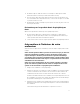
Si vous avez un cabinet de rack 42 U, faites glisser le rabat du bouton-poussoir du loquet aussi loin que possible, appuyez sur le bouton-poussoir, tournez la poignée dans le sens des aiguilles d'une montre jusqu'à ce que le loquet se libère, puis ouvrez la porte en la tirant (reportez-vous à la Figure 2-3). capuchon du boutonpoussoir boutonpoussoir poignée support.dell.
2. Retirez du rack la porte avant. Si vous avez un cabinet de rack 24 U, suivez les étapes ci-après (reportez-vous à la Figure 2-4) : a. Pendant que la porte est ouverte, enlevez et retirez entièrement toutes les broches de charnière. b. Retirez les portes avec précaution.
Si vous avez un cabinet de rack 42 U, suivez les étapes ci-après (reportez-vous à la Figure 2-5) : a. Une personne doit empoigner le haut de la porte pour la stabiliser. Quelqu’un d'autre doit tenir le bas de la porte. b. La personne tenant le bas de la porte doit appuyer sur le levier d'éjection sur la charnière du bas, puis éloigner le bas de la porte du cabinet de rack d'une dizaine de centimètres. c.
REMARQUE : Si les assemblages de glissières ont été installés auparavant par Dell, vous pouvez sauter cette section. Vous devez laisser libre 2 U (3,5 pouces ou 9 centimètres) d'espace vertical pour chaque commutateur PowerVault 56F que vous installez dans le rack. REMARQUE : Les rails verticaux du rack portent des petites marques par incrément de 1 U (reportez-vous à la Figure 2-6).
1. Mettez l'avant du modèle sur les rails verticaux à l'avant du rack, à l'endroit où vous désirez installer le commutateur. Assurez-vous que ce qui est imprimé sur le modèle identifie le côté orienté vers l'extérieur comme étant l'avant du modèle. 2. Marquez les rails verticaux avant du rack avec une feutre ou mettez du ruban cache adhésif sur les bords supérieur et inférieur du commutateur (reportez-vous à la Figure 2-7).
rail vertical commutateur assemblage à glissière rail à glissière ' ( $ % $$ 2-10 5. Poussez vers le bas et vers l'avant jusqu'à ce que les languettes de montage soient bien installées dans les orifices carrés sur le rail vertical et que le boutonpoussoir ressorte en faisant entendre un « clic ». 6.
La section suivante présente des instructions pour l'installation du commutateur PowerVault 56F dans le rack. ' " '('$" - % - , 3 < ) 1 3 ! " #$ ' % .
! " #$ ) % . - 7 = Pour remettre en place les portes avant et arrière d'un rack 24 U, suivez les étapes ci-après : 1. Soulevez la porte avant et alignez les broches des charnières avec l'arbre de charnière dans le rack, comme indiqué à la Figure 2-4. 2.
% & assemblages de glissières illustration, 2-2 installation dans le rack, 2-8 décharge électrostatique.
! outils recommandés, 2-2 rails verticaux marquage, 2-9 une unité de rack, 2-8 portes ouverture du loquet, 2-3, 2-4, 2-5 remise en place, 2-12 retrait, 2-3, 2-6, 2-7 portes du rack ouverture du loquet, 2-4, 2-5 retrait, 2-3, 2-6, 2-7 rampe illustration, 2-2 installation dans le rack, 2-11 retrait des portes du rack, 2-3 " site Web de Dell, 2-8 précautions, iii # unité de rack, 2-8 2 Guide d'installation en rack des systèmes Dell PowerVault 56F