
Storage System Hardware Owner's Manual
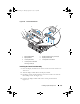
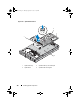
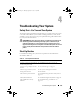
Table Of Contents
- Hardware Owner’s Manual
- About Your System
- Using the System Setup Program
- Installing System Components
- Recommended Tools
- Inside the System
- Front Bezel
- Opening and Closing the System
- Hard Drives
- Replacing a Hard-Drive Carrier
- Power Supplies
- System Fans
- Cooling Shroud
- Fan Brackets
- Cable Routing
- SAS Controller Daughter Card
- Configuring the Boot Device
- Expansion Cards
- Expansion-Card Cage
- DRAC Card and Cables
- Optical Drive and Cable
- System Memory
- Activating the Integrated NIC TOE
- Processors
- System Battery
- Expansion-Card Riser Boards
- Sideplane Board
- SAS Backplane Board
- Control Panel Assembly (Service-only Procedure)
- System Board (Service-only Procedure)
- Troubleshooting Your System
- Safety First-For You and Your System
- Start-Up Routine
- Checking the Equipment
- Troubleshooting Basic I/O Functions
- Troubleshooting a NIC
- Troubleshooting a Wet System
- Troubleshooting a Damaged System
- Troubleshooting the System Battery
- Troubleshooting Power Supplies
- Troubleshooting System Cooling Problems
- Troubleshooting System Memory
- Troubleshooting an Optical Drive
- Troubleshooting an External SCSI Tape Drive
- Troubleshooting a Hard Drive
- Troubleshooting a SAS Controller Daughter Card
- Troubleshooting Expansion Cards
- Troubleshooting the Microprocessors
- Running the System Diagnostics
- Jumpers and Connectors
- Getting Help
- Glossary
- Index
Installing System Components 123
Figure 3-27. Control Panel Removal
Installing the Control Panel Assembly
1
Insert the display module into the chassis cutout and secure with the two
Torx screws.
2
Affix the display module label to the display module.
3
Install the control panel board in the system chassis and secure with the
three Phillips screws. See Figure 3-27.
4
Connect the display module cable to the control panel board. See
Figure 3-27.
1 display module label 2 display module securing screws (2)
3 display module 4 display module cable
5 control panel cable 6 control panel circuit board
7 control-panel circuit board
securing screws (3)
5
6
2
7
1
3
4
Book.book Page 123 Monday, September 14, 2009 12:57 PM